Dynamic load balancing of distributed parity in a raid array

a distributed parity and raid array technology, applied in the field of distributed parity disk arrays and data storage computers, can solve the problems of loss of access to data on the disk, parity disk becoming a performance bottleneck, and the allocating of new raid arrays to accommodate increasing data storage requirements is typically less than ideal, so as to achieve the effect of disrupting the assignment of parity blocks

Active Publication Date: 2013-11-14
NETWORK APPLIANCE INC
View PDF3 Cites 3 Cited by
  • Summary
  • Abstract
  • Description
  • Claims
  • Application Information

AI Technical Summary

Benefits of technology

[0014]Redistributing parity blocks within an DPDA upon the addition of a new disk to the DPDA in accordance with the present invention results in parity blocks being evenly distributed across the disks of the DPDA. The disruption of parity block assignments existing before the addition of the new disk is minimized during the redistribution of parity blocks within the DPDA. Parity blocks are also redistributed in DPDA-MPs without the possibility of selecting two or more parity blocks within the same stripe of a parity pattern for transfer to the new disk.

Problems solved by technology

Disks, like other electronic devices, are prone to occasional failures which can result in a loss of access to the data on the disk.
Although the use of RAID levels 3 or 4 may be desirable in certain situations, continual write operations to the dedicated parity disk can result in the parity disk becoming a performance bottleneck.
Allocating a new RAID array to accommodate increasing data storage requirements is typically less than ideal because the new RAID array may have much more data storage space than will be needed or used in the immediate future.
Most RAID controllers can create or delete a striped distributed parity RAID array, but are not typically functional to expand the array by adding a new disk once the array has been created.
One of the challenges involved in adding a new disk to an existing array is determining how to redistribute the parity blocks across the disks of the array evenly (i.e., each disk has substantially the same number of parity blocks).
Redistributing parity blocks is especially challenging in distributed parity RAID arrays having dual or higher order parity, since care must be taken to avoid attempting to assign two parity blocks from the same stripe to the new disk.

Method used


Image

  • Dynamic load balancing of distributed parity in a raid array
  • Dynamic load balancing of distributed parity in a raid array
  • Dynamic load balancing of distributed parity in a raid array

Examples


Embodiment Construction

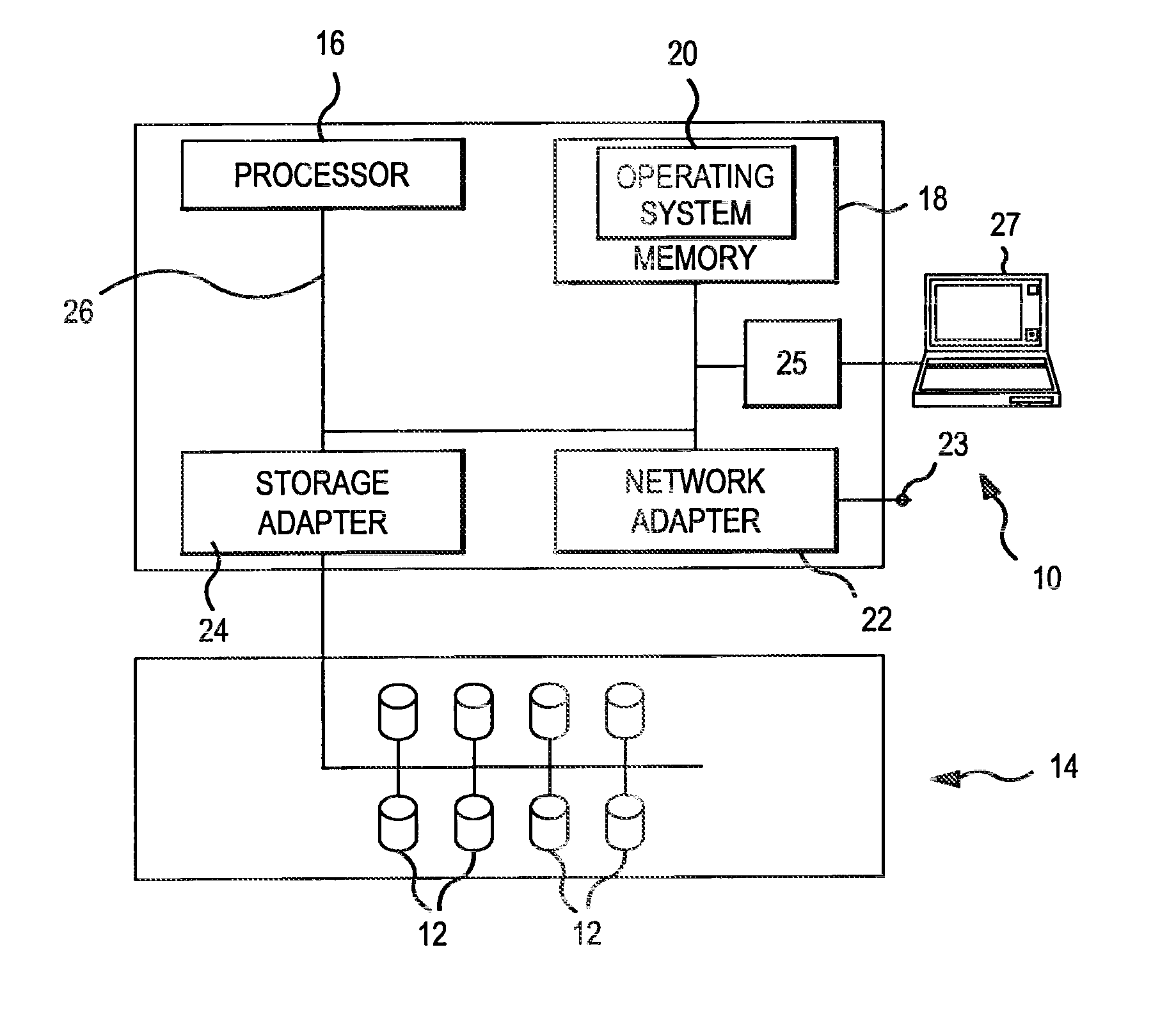
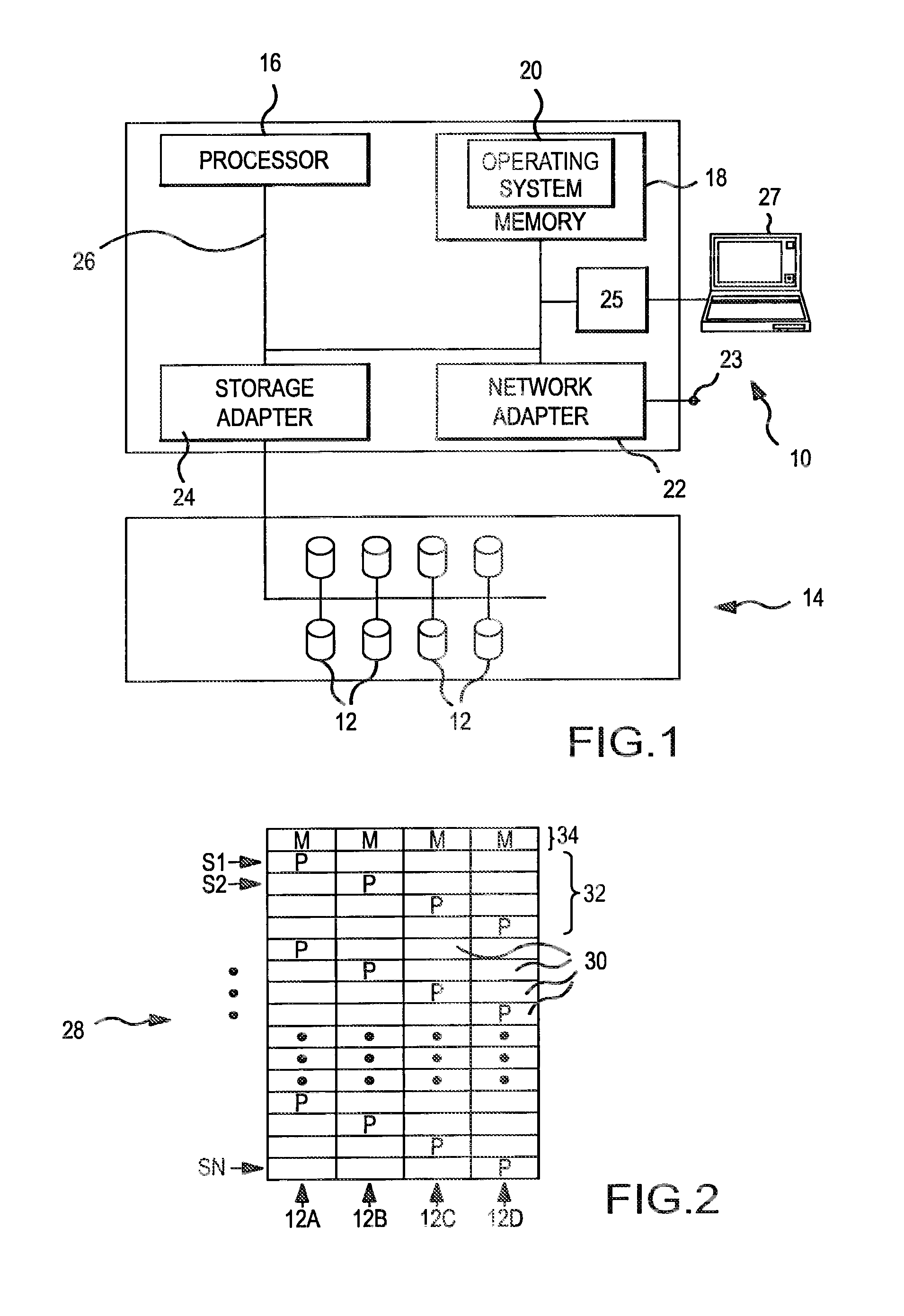
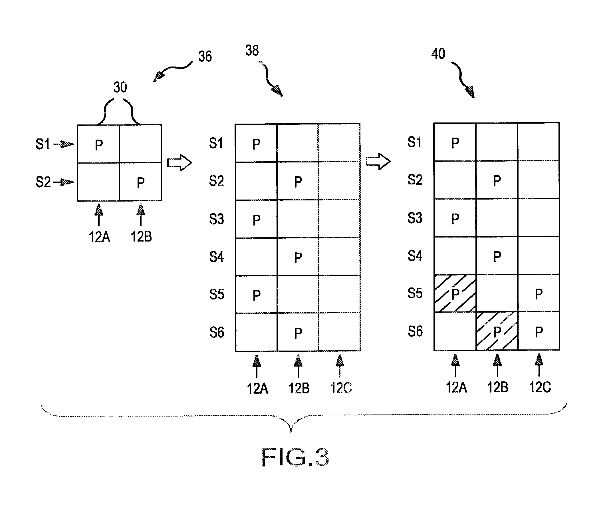
[0026]The present invention involves the use of a parity pattern which defines a repeated distribution of parity blocks within a distributed parity disk array (UDPDA″). The parity pattern is a logical construct that may be stored within a memory or other data storage medium as a data structure, such as an array, containing information that identifies or facilitates identification of the blocks within a stripe of the DPDA which are designated as parity blocks. The parity pattern is modified when a new disk is added to the DPDA, resulting in a new parity pattern for use with the DPDA. The parity blocks within the DPDA are redistributed by transferring a minimal number of parity blocks within the DPDA to the new disk in accordance with the new parity pattern resulting in an even distribution of parity blocks throughout the DPDA. The parity blocks in DPDA's having dual or higher order parity are redistributed without the possibility of inadvertently selecting two parity blocks within th...


PUM


Abstract

A parity pattern defines a repeated distribution of parity blocks within a distributed parity disk array (“DPDA”). The parity pattern identifies on which disks the parity block or blocks for a stripe are located. When a new disk is added to the DPDA, the parity pattern is modified so that the distribution of parity blocks within the parity pattern is even. Parity blocks within the DPDA are then redistributed to conform with the modified parity pattern.

Description

CROSS REFERENCE OF RELATED APPLICATIONS[0001]This application is a Continuation Application of and claims priority to U.S. application Ser. No. 12 / 237,138, entitled “DYNAMIC LOAD BALANCING OF DISTRIBUTED PARITY IN A RAID ARRAY”, filed Sep. 24, 2008.FIELD OF THE INVENTION[0002]This invention relates to distributed parity disk arrays and data storage computers. More particularly, the present invention relates to a new and improved method and apparatus for dynamically reallocating parity information across a distributed parity disk array when a new disk is added to the disk array.BACKGROUND OF THE INVENTION[0003]Hard disk drives (“disks”) are common data storage devices used in conjunction with computers. Computers typically store data either on locally attached disks or on a remote data storage server computer which has its own locally attached disks. Disks, like other electronic devices, are prone to occasional failures which can result in a loss of access to the data on the disk. A ...

Claims


Application Information

Patent Timeline
Patent Type & Authority Applications(United States)
IPC IPC(8): G06F12/00
CPCG06F12/00G06F2211/1028G06F11/1076
Inventor GOEL, ATUL
Owner NETWORK APPLIANCE INC
Why Eureka
Try Eureka