Tension Stiffened and Tendon Actuated Manipulator and a Hinge for Use Therein

Active Publication Date: 2013-11-21
NASA
View PDF9 Cites 5 Cited by
  • Summary
  • Abstract
  • Description
  • Claims
  • Application Information

AI Technical Summary

Benefits of technology

This patent text describes a device that can move like a robot to collect and manipulate objects in space. The device is made up of link arms and a hinge that allows the arms to rotate, along with a system for tensioning and actuating the hinge using cables and non-driven elements. The device can be used in zero-gravity environments or on planets with gravity. The technical effect is a versatile and adaptable tool for manipulating payloads in a robotic-like manner.

Problems solved by technology

It has been concluded that conventional (Earth-based) robotic manipulator configurations would have extreme difficulty meeting planetary surface requirements because their mass increases rapidly with increases in reach and payload handling mass.
In Earth-bound applications, cranes are mass efficient devices that have long reach and high payload capability, but cranes lack the dexterity and versatility found in robotic manipulators.
Cable stiffened structures have also been developed for many space applications and structures, but have never been considered as components in a space robotic manipulator.
At some point, increasing tube diameter becomes impractical because of either packaging limitations, or the size of the tube impedes operations, or the ability to reach into tight spaces.
As the required reach for a manipulator increases, a conventional configuration suffers from the same rapid increase in mass as a ground-based manipulator.
The manipulator architecture of the SRMS and SSRMS has limited scalability.
In addition, the architecture does not lend itself to on-orbit repair, requiring the entire device to be returned to Earth for routine maintenance or repair.

Method used


Image

  • Tension Stiffened and Tendon Actuated Manipulator and a Hinge for Use Therein
  • Tension Stiffened and Tendon Actuated Manipulator and a Hinge for Use Therein
  • Tension Stiffened and Tendon Actuated Manipulator and a Hinge for Use Therein

Examples


Embodiment Construction

[0041]While the invention may be susceptible to embodiment in different forms, there is shown in the drawings, and herein will be described in detail, a specific embodiment with the understanding that the present disclosure is to be considered an exemplification of the principles of the invention, and is not intended to limit the invention to that as illustrated and described herein. Therefore, unless otherwise noted, features disclosed herein may be combined together to form additional combinations that were not otherwise shown for purposes of brevity.

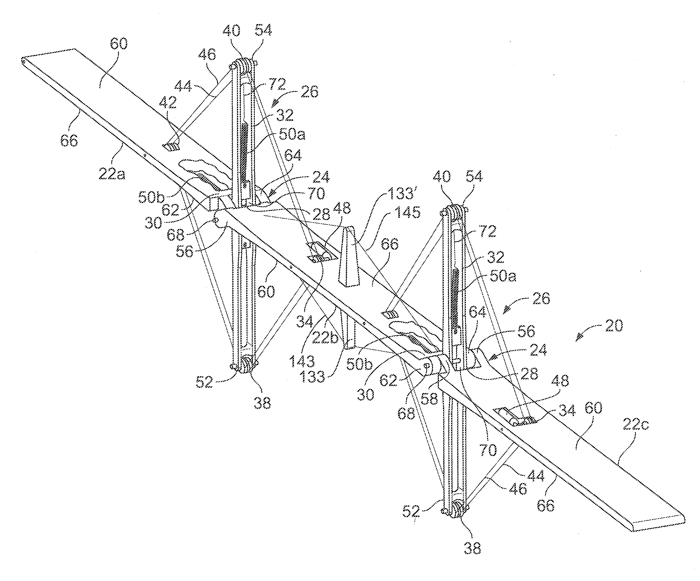
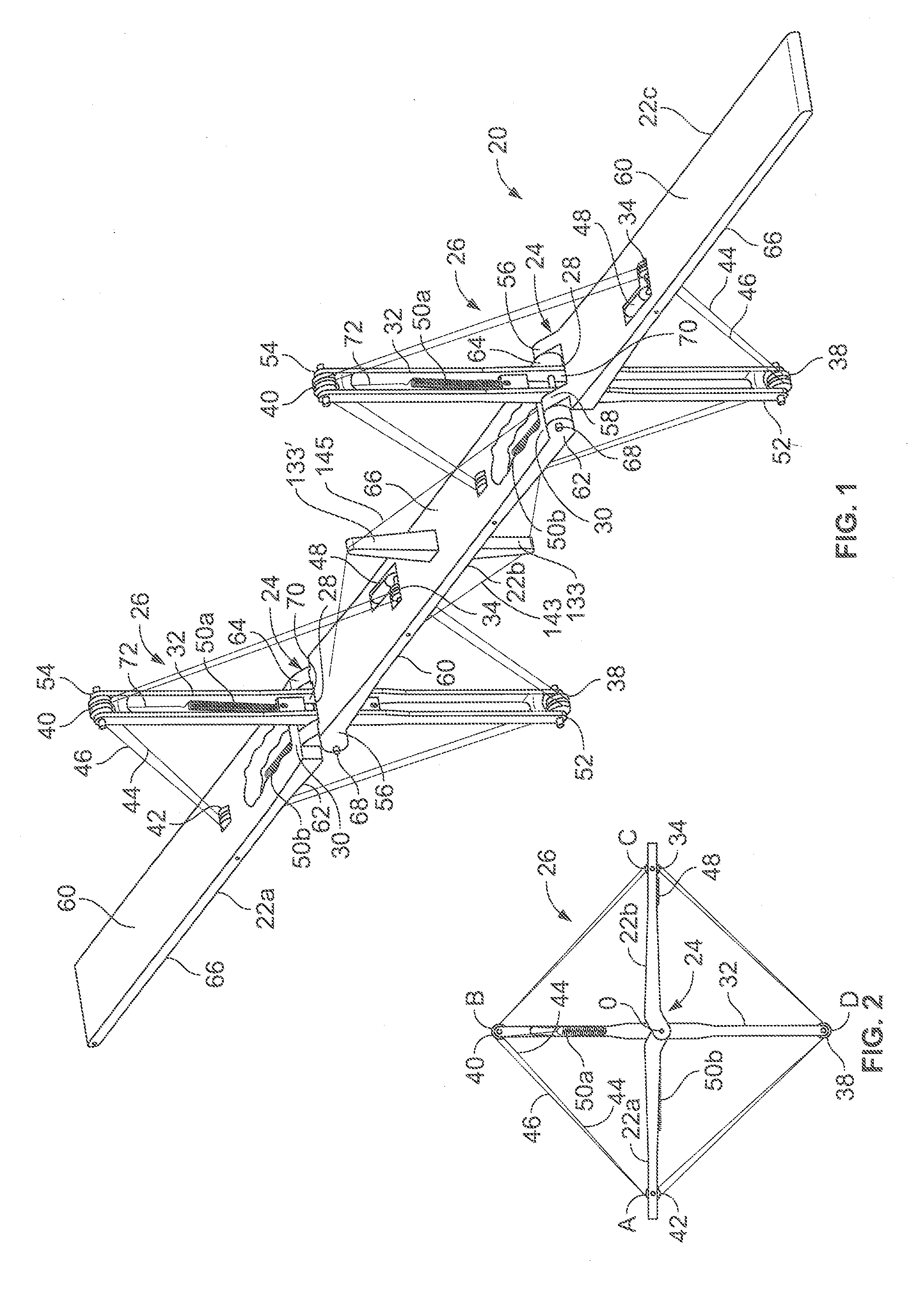
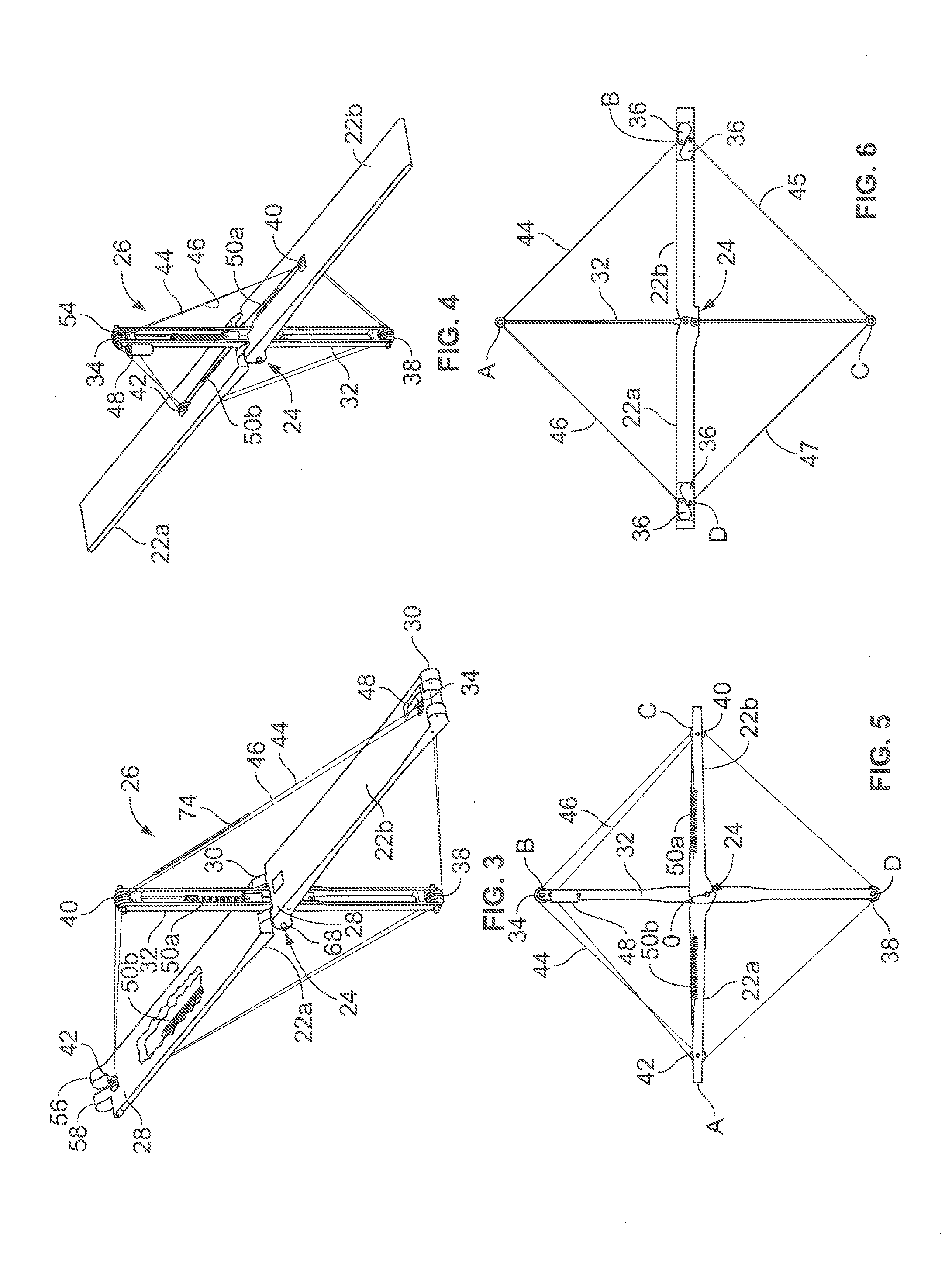
[0042]A manipulator 20 has a plurality of link arms 22a, 22b, 22c which are connected together by hinges 24. The manipulator 20 has a cable actuation and tensioning system 26 which actuates the hinges 24 and stiffen the structure of the manipulator 20 in a modular fashion. The manipulator 20 achieves both high structural performance, as well as high dexterity by combining a number of tendon-actuated hinges 24 with extendable-length li...


PUM


Abstract

A tension stiffened and tendon actuated manipulator is provided performing robotic-like movements when acquiring a payload. The manipulator design can be adapted for use in-space, lunar or other planetary installations as it is readily configurable for acquiring and precisely manipulating a payload in both a zero-g environment and in an environment with a gravity field. The manipulator includes a plurality of link arms, a hinge connecting adjacent link arms together to allow the adjacent link arms to rotate relative to each other and a cable actuation and tensioning system provided between adjacent link arms. The cable actuation and tensioning system includes a spreader arm and a plurality of driven and non-driven elements attached to the link arms and the spreader arm. At least one cable is routed around the driven and non-driven elements for actuating the hinge.

Description

CROSS-REFERENCE TO RELATED APPLICATION[0001]This patent application is a continuation of Patent Cooperation Treaty patent application number PCT / US13 / 24321, filed Feb. 1, 2013, which claims the benefit of and priority to U.S. Provisional Application Ser. No. 61 / 594,115, filed Feb. 2, 2012. The contents of each of the foregoing are hereby incorporated by reference in their entireties.STATEMENT REGARDING FEDERALLY SPONSORED RESEARCH AND DEVELOPMENT[0002]The invention described herein was made in the performance of work under NASA contracts and by employees of the United States Government and is subject to the provisions of 51 U.S.C. §20135 and 35 U.S.C. §202, and may be manufactured and used by or for the Government of the United States of America for governmental purposes without the payment of any royalties thereon or therefor. In accordance with 35 U.S.C. §202, the contractor elected not to retain title.FIELD OF THE INVENTION[0003]The present invention relates to tension stiffened ...

Claims


Application Information

Patent Timeline
IPC IPC(8): B25J18/00B25J17/00
CPCB25J18/00B25J17/00B25J9/06B25J9/1045B64G2004/005Y10T74/20329Y10T74/20323B66C23/68
Inventor DOGGETT, WILLIAM R.DORSEY, JOHN T.GANOE, GEORGE G.KING, BRUCE D.JONES, THOMAS C.MERCER, CHARLES D.CORBIN, COLE K.
Owner NASA
Why Eureka
Try Eureka