Gradient sensor

Active Publication Date: 2020-05-07
WOODS HOLE OCEANOGRAPHIC INSTITUTION
View PDF3 Cites 1 Cited by
  • Summary
  • Abstract
  • Description
  • Claims
  • Application Information

AI Technical Summary

Benefits of technology

[0011]An object of the present invention is to provide an improved gradient sensing device

Problems solved by technology

Existing underwater gradient measurement systems are capable of collecting and recording marine physical gradients, however most designs have not changed in many years and these systems are imprecise, difficult to build devices with low resolution of gradient sensing.
Sensor data is then stored onboard the device, with limited data relay capabilities and no real-time, operational control of the deployed device.
However, existing heat flow probe technology suffers from 1) inadequate gradient sensing resolution, 2) handling and transport difficulties due to size and weight, 3) insufficient real-time data communication transfer capabilities, 4) imprecise position and orientation sensing, and 5) inappropriate probe design (e.g. length) for changing target mediums in an area of interest.
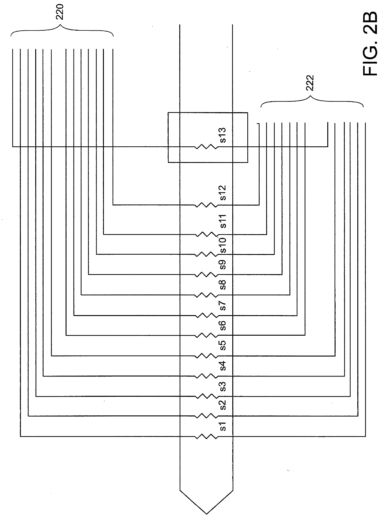
HFPs of the art are limited by the number of sensors they can incorporate into their design.
This drawback physically limits the resolution and data accuracy by limiting the number of sensors, typically to less than about 10 sensors, and introduces significant thermal mass issues which may alter readings.
Running analog sensor output wires from the bow string sensor to the housing also increases the complexity of the connections between these components.
Complex electrical connections introduce signal noise between the sensors, reducing the data limits of detection, resolution and accuracy.
Complex connections also pr

Method used


Image

  • Gradient sensor
  • Gradient sensor
  • Gradient sensor

Examples


Example

DEFINITIONS

[0033]Waterproof. As used herein, the terms “waterproof,”“water-tight,” and “fluid-tight” describe the ability of a construct to withstand the entry of water or other fluid. The water may be fresh water (e.g. from a lake), salt water (e.g. ocean water) or other water-based fluid. Unless otherwise stated, the term waterproof also denotes pressure resistant, and a pressurized container, capable of withstanding external pressures that correlate with any depth up to 6000 meters of water depth.

[0034]Support structure. “Support structure” as defined herein refer to physical structure that defines (e.g. houses or supports) parts of the inventive device and are referred to as “support structure” or a simply “support”. A support structure is a physical construction in or on which the sensing segment is located. In some embodiments, a support structure also houses parts of the invention. In the instant invention, the first support structure supports the sensing segment, and the sen...


PUM


Abstract

A gradient sensing probe system, and method of using same, including a sensing segment which includes a plurality of sensors, a support structure, and an electrical interface having first and second faces. The system further includes a housing, a power source, and an electronics package including a controller and disposed within the housing. The sensing segment is configured to measure external gradients and to exchange data with the controller. The power source is connected energetically to provide power to the sensing segment and the electronics package, and is controlled by the controller.

Description

CROSS REFERENCE TO RELATED APPLICATIONS[0001]This application claims priority to U.S. Provisional Application No. 62 / 537,113 filed on Jul. 26, 2017, the contents of which are hereby incorporated as if set forth herein in its entirety.FIELD OF THE INVENTION[0002]This invention relates to systems and methods for measuring differential gradients in target media, and more particularly to a probe system for measuring gradients (e.g. thermal) or other physical properties of marine sediments.BACKGROUND[0003]The precise measurement of physical and chemical gradients in fluid and marine environments is a requirement for many oceanographic pursuits. Understanding magnetic, thermal, acid, and vibrational gradients in underwater environments has importance in both basic research and in applied areas such as oil, gas and ore exploration and development. Gradient measurements contribute to our knowledge of the composition of sea floor sediments, subduction zones, marine sea mounts and ridges.[000...

Claims


Application Information

Patent Timeline
IPC IPC(8): G01K17/08G01K13/00G01K1/02G01C9/02
CPCG01K17/08G01K13/00G01K2215/00G01K1/026G01C9/02G01C13/00
Inventor SANGER, RICHARDFUCILE, PAUL D.TIVEY, MAURICE
Owner WOODS HOLE OCEANOGRAPHIC INSTITUTION
Why Eureka
Try Eureka