On-load tap-changer control method, excitation control system carrying out said control method and power excitation chain

Active Publication Date: 2013-11-21
GENERAL ELECTRIC TECH GMBH
View PDF1 Cites 12 Cited by
  • Summary
  • Abstract
  • Description
  • Claims
  • Application Information

AI Technical Summary

Benefits of technology

[0013]One object of the present invention is to simplify the overall power generation chain and to propose a more secure

Problems solved by technology

However, if the reactive power flow is controlled, this can only be done indirectly via voltage regulation, and the reference value for the voltage regulator has to be set manually in a try-and-see approach by the ope

Method used


Image

  • On-load tap-changer control method, excitation control system carrying out said control method and power excitation chain
  • On-load tap-changer control method, excitation control system carrying out said control method and power excitation chain
  • On-load tap-changer control method, excitation control system carrying out said control method and power excitation chain

Examples


Example

[0051]In all figures, same reference numerals refer to the same elements.

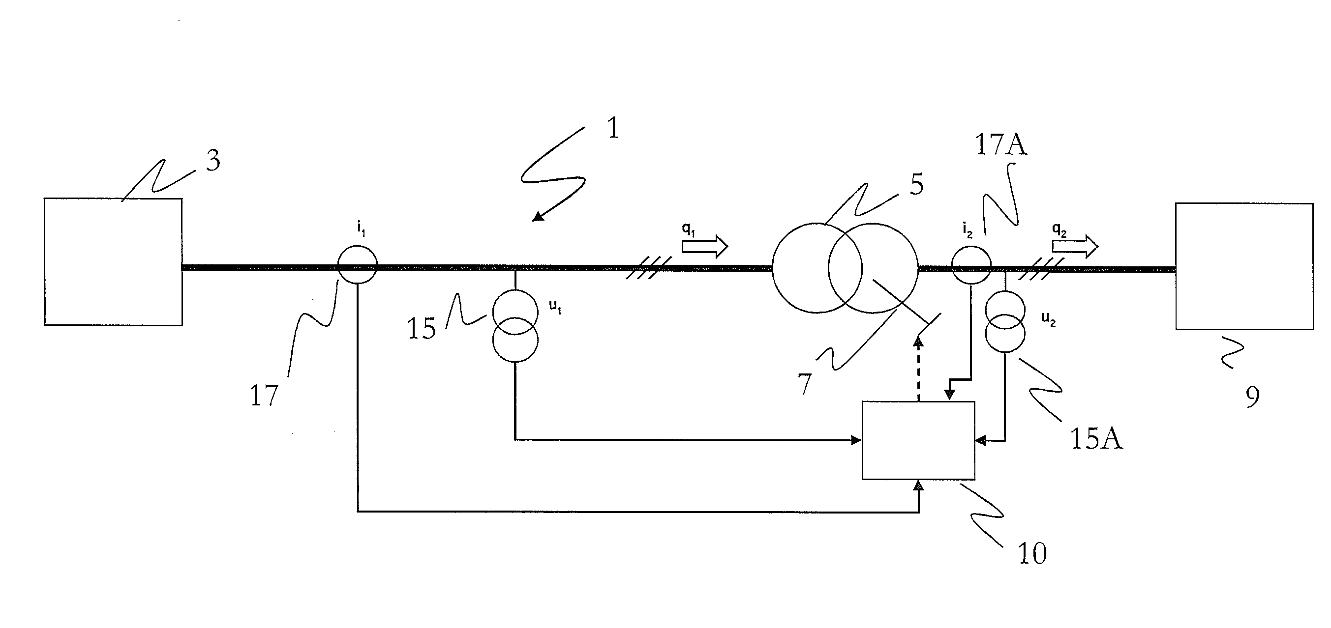
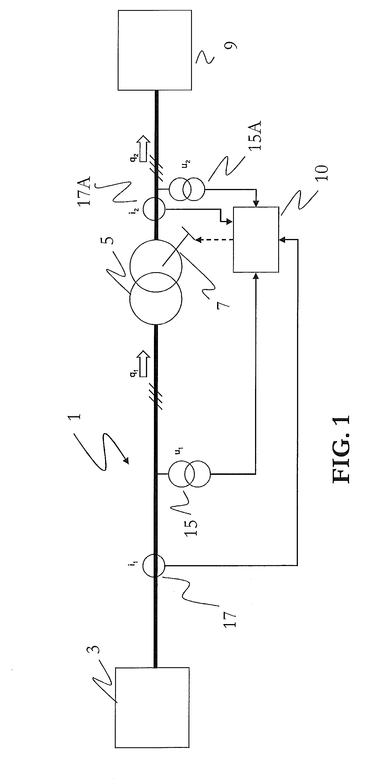
[0052]FIG. 1 is a schematic representation showing a first grid 3 in which electric power is generated connected to the primary side of a power transformer 5, equipped with an on-load tap changer OLTC 7.

[0053]The secondary side of the power transformer 5 is connected to a second grid 9 in which electrical power is consumed.

[0054]The flow of power is counted positive from the primary to the secondary side of the power transformer 5.

[0055]The power transformer is connected to an associated OLTC regulator and control unit 10.

[0056]Said OLTC regulator and control unit 10 is configured to measure the voltage and current on the primary side u1, i1 or on the secondary side u2 i2 of the power transformer or on both, the primary side u1, i1 and on the secondary side u2, i2 of the power transformer 5.

[0057]As shown in FIG. 1, said OLTC regulator and control unit 10 has inputs that are respectively connected to measuremen...


PUM


Abstract

The present invention relates to an on-load tap changer control method for a power transformer in a power system. The power transformer has a primary side for a connection to a first grid in which electric power is generated, and a secondary side for connection to a second grid in which electrical power is consumed, the power transformer being equipped with an on-load tap changer. The method includes measuring the voltage and current at least on the primary side (u1, i1) or on the secondary side (u2 i2) of the power transformer, processing said measured voltages (u1; u2) and currents (i1; i2) in order to derive prospective reactive power at the output of the power transformer after prospective tap-change, comparing prospective reactive power to a predefined set-point, and initiating tap-change of on-load tap changer if prospective reactive power is closer to said predefined set-point than actual reactive power.

Description

CROSS-REFERENCE TO RELATED APPLICATIONS[0001]This application claims priority to PCT / EP2012 / 050514 filed Jan. 13, 2012, which claims priority to European Application 11152800.6 filed Jan. 31, 2011, both of which are hereby incorporated in their entireties.TECHNICAL FIELD[0002]The present invention relates to an on-load tap changer control method, an excitation control system carrying out said control method and a power excitation chain for regulating the reactive power flow over a power transformer equipped with an on-load tap changer (OLTC). It can be used in particular for step-up transformers equipped with OLTCs in power plants for the generation of electrical power.BACKGROUND OF THE INVENTION[0003]In power systems, on-load tap changers (OLTCs) are mainly employed in two applications:[0004]in distribution networks, they are used to keep the voltage close to its nominal value.[0005]in transmission networks, they are used to regulate the flow of reactive power in the system.For exa...

Claims


Application Information

Patent Timeline
IPC IPC(8): G05F1/70
CPCG05F1/70H02J3/1878Y02E40/30
Inventor MEINECKE, CARSTEN
Owner GENERAL ELECTRIC TECH GMBH
Why Eureka
Try Eureka