
Capstan comprising means for assessing the tension of a line wound around it and means for the automatic selection of at least one speed as a function of said tension.

a technology of capstan and tension, which is applied in the direction of winding mechanism, hoisting equipment, etc., can solve the problems of not allowing the crew member to pump between the first and second positions, complicated maneuvers for the crew members, and inability to adapt the winch to the position

Inactive Publication Date: 2013-11-28
PONTOS
View PDF45 Cites 6 Cited by
  • Summary
  • Abstract
  • Description
  • Claims
  • Application Information

AI Technical Summary

Benefits of technology

This patent describes a new kind of winch that automatically adjusts the speed of its gears based on the tension of the rope or wire around the drum. This makes it easier for the person tensioning the rope to match their physical condition. The winch also has a modular design, which reduces its manufacturing costs.

Problems solved by technology

Prior art winches have the drawback whereby, to get into third gear speed, it is necessary to reverse the direction of rotation of the lever and actuate the push-button provided on the winch.
This operation tends to make the maneuvers more complex for the crew members when they are sailing in difficult conditions (such as a choppy sea, a congested deck, etc).
This makes the maneuver more complicated.
However, this technique has the drawback of not allowing the crew member to pump between the first and second gear speeds and then between the second and third gear speeds.
There is therefore no existing winch that enables pumping between the first and second gear speeds and then between the second and third gear speeds through action only on the direction of rotation of the lever.
Nor do present-day winches make it possible to match the passage from pumping between the first and second gear speeds to pumping between the second and third gear speeds with the arm strength of the crew member in charge of rotating the lever of the winch.
Present-day winches therefore cannot be used to obtain both high speeds of winding of the line and high winding torque values.
Present-day winches cannot be used for the automatic selection of a gear speed according to the tension of the line wound around the winch.
This complicates the maneuvers performed by crew members sailing in a difficult context (a choppy sea or a congested deck).
Nor does any winch make it possible to adapt the gear ratio to the tension in the line.

Method used


Image

  • Capstan comprising means for assessing the tension of a line wound around it and means for the automatic selection of at least one speed as a function of said tension.
  • Capstan comprising means for assessing the tension of a line wound around it and means for the automatic selection of at least one speed as a function of said tension.
  • Capstan comprising means for assessing the tension of a line wound around it and means for the automatic selection of at least one speed as a function of said tension.

Examples


first embodiment

[0092]1.2. Example of a Winch According to the Invention

[0093]1.2.1. Architecture

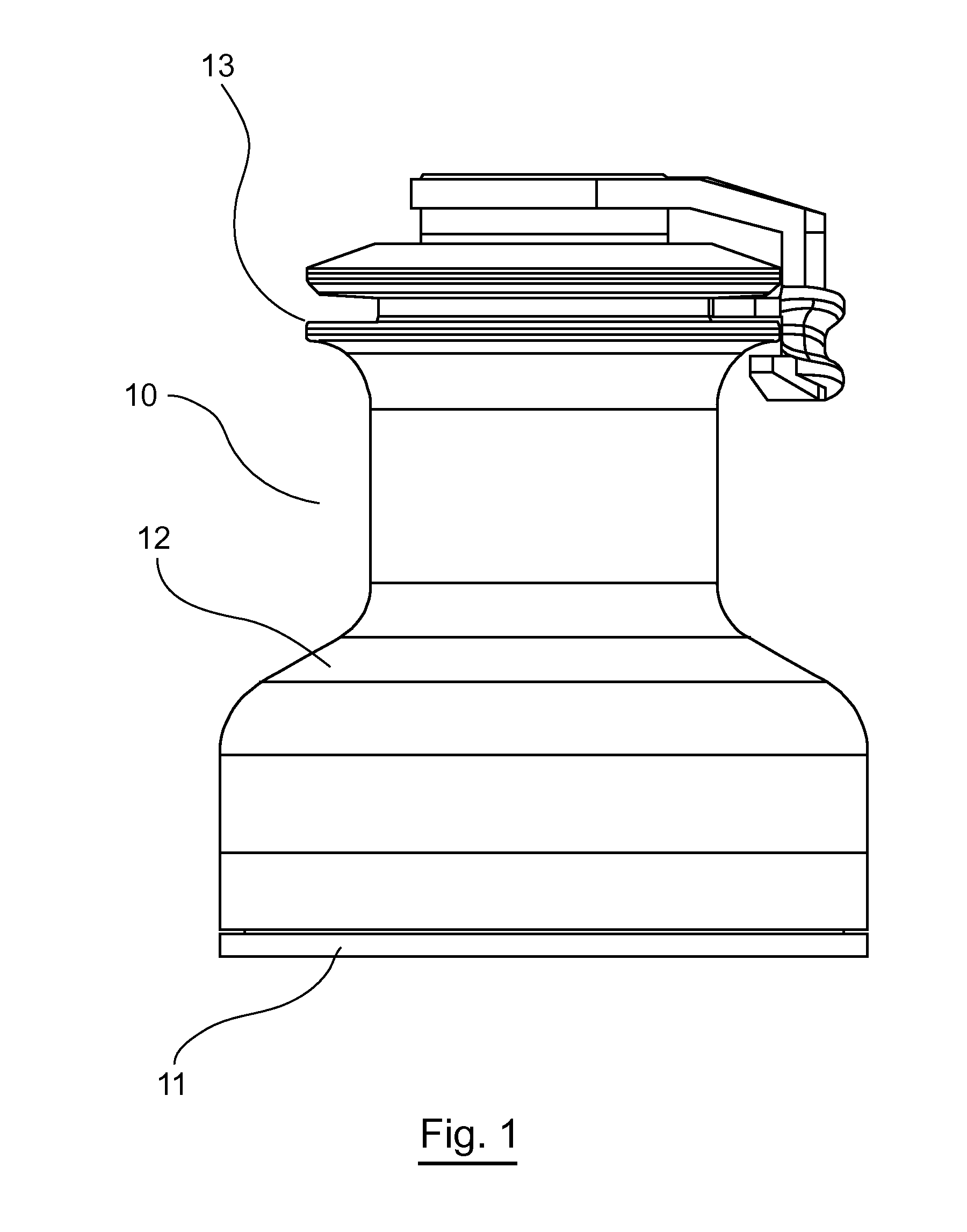
[0094]FIG. 1 illustrates a front view of a winch 10 according to the invention. Such a winch 10 comprises a frame 11 on which there is mounted a drum 12 that is mobile in rotation. The frame 11 is to be fixedly attached for example to the deck of a sailing boat. A line, one end of which is connected to a sail of the sailing boat, can be wound around the drum 12. This winch 10 classically comprises a device 13 for reversibly capturing one end of the line that has to be wound around the drum 12.

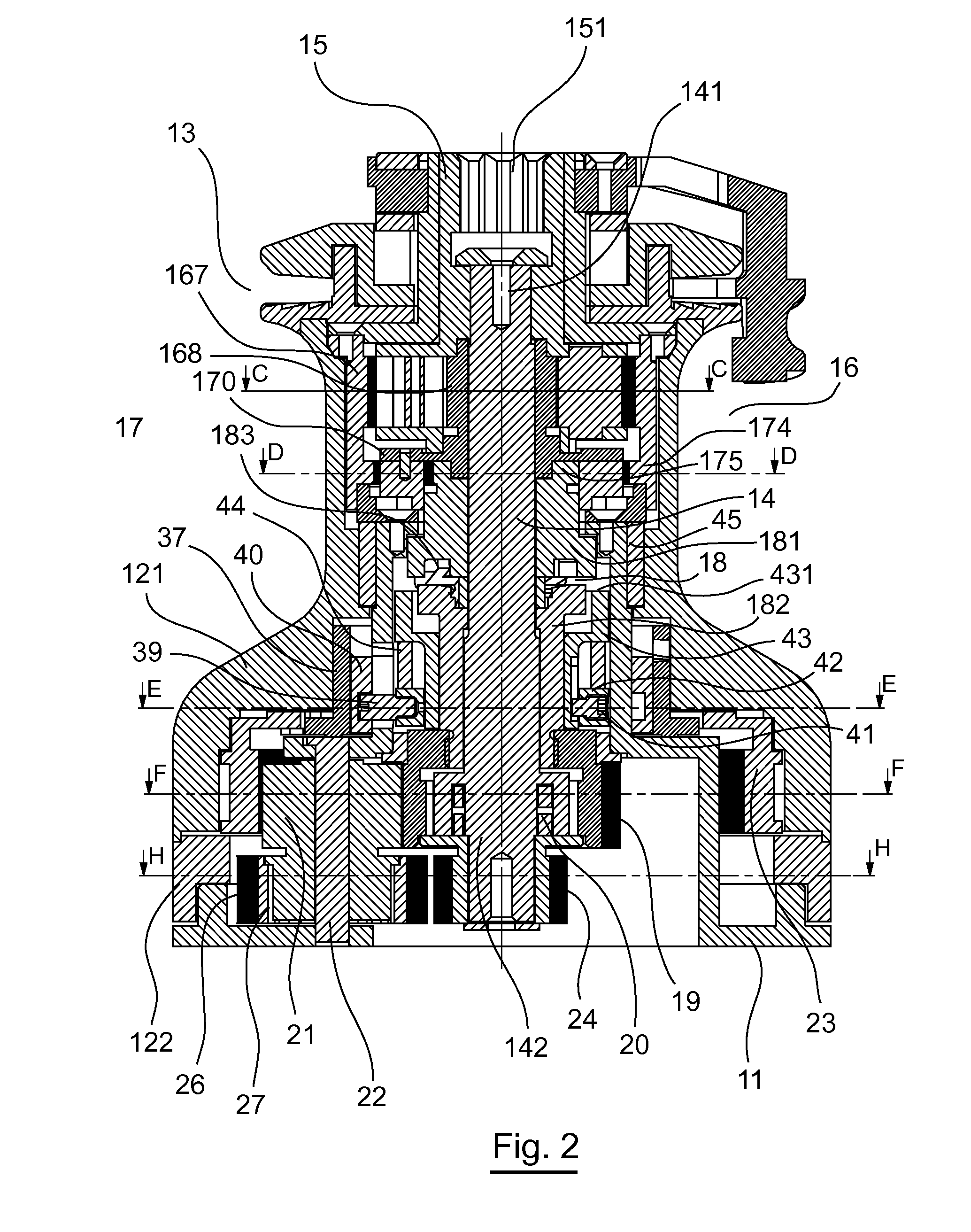
[0095]FIG. 2 is a view in section of the winch 10 illustrated in FIG. 1.

[0096]As can be seen in this FIG. 2, the drum 12 comprises an upper drum element 121 and a lower drum element 122.

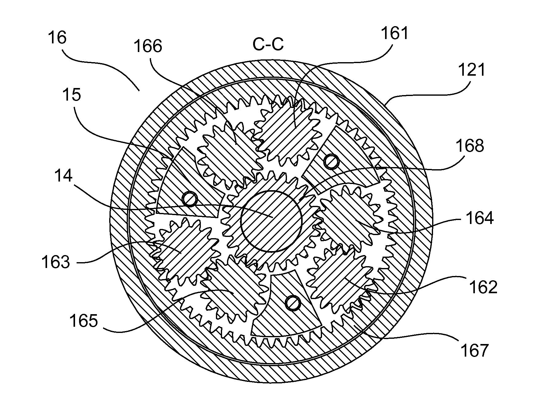
[0097]The winch comprises a shaft 14 mounted rotationally in the frame 11. The shaft 14 comprises an upper end 141. This upper end 141 is interdependent with the input 15 of the winch. The input 15 has a splined portion 151 which is...

second embodiment

[0156]1.3. Example of a Winch According to the Invention

[0157]1.3.1. Architecture

[0158]FIGS. 10 and 11 illustrate two views in longitudinal section of a winch according to a second embodiment.

[0159]Such a winch 10 comprises a frame 11 on which a drum 12 is mounted so as to be mobile in rotation. The frame 11 is to be fixedly attached for example to the deck of a sailing boat. A line, one end of which is linked to a sail of the sailing boat, can be wound around the drum 12. This winch 10 classically comprises a device 13 for reversibly capturing one end of the line that has to be wound around the drum 12.

[0160]The drum 12 comprises an upper drum element 121 and a lower drum element 122.

[0161]The winch comprises a first shaft portion 200 mounted so as to be mobile in rotation in the frame 11. The first shaft portion 200 comprises one upper end 201. This upper end 201 is interdependent with the input 15 of the winch. The input 15 has a splined portion 151 designed to cooperate with mea...

third embodiment

[0250]1.4. Example of a Winch According to the Invention

[0251]1.4.1. Architecture

[0252]Referring now to FIGS. 19 to 25, a winch is presented according to a third embodiment of the invention.

[0253]Such a winch 10 comprises a frame 11 on which a drum 12 is mounted so as to be mobile in rotation. The frame 11 is to be fixedly attached for example to the deck of a sailing boat. A line, one end of which is linked to a sail of the sailing boat; can be wound around the drum 12. This winch 10 classically comprises a device 13 for reversibly capturing one end of the line that has to be wound around the drum 12.

[0254]The drum 12 comprises an upper drum element 121 and a lower drum element 122.

[0255]The winch comprises a first shaft portion 200 mounted so as to be mobile in rotation in the frame 11. The first shaft portion 200 comprises one upper end 201. This upper end 201 is interdependent with the input 15 of the winch. The input 15 has a splined portion 151 designed to cooperate with means...


PUM


Abstract

A capstan is provided for being secured to a sailing craft in order to tension a line attached to a sail. The capstan includes a fixed base housing a shaft and a gearbox, a barrel around which the line can be wound, the barrel being mounted such that it is capable of rotating in just one direction around the base and connected to the shaft via the gearbox. The rotation of the shaft is accompanied by rotating of the barrel about the base. The capstan includes elements for assessing the tension in the line and for selecting at least one speed when the tension exceeds a predetermined threshold. The gearbox includes an interior annulus, the annulus being mounted such that it can rotate inside the barrel against the effect of elements that apply a friction and / or elastic return force to the annulus so that it can turn in relation to the barrel when the tension is above the threshold.

Description

CROSS-REFERENCE TO RELATED APPLICATIONS[0001]This application is a Section 371 National Stage Application of International Application No. PCT / EP2011 / 067750, filed Oct. 11, 2011, which is incorporated by reference in its entirety and published as WO 2012 / 049188 on Apr. 19, 2012, not in English.STATEMENT REGARDING FEDERALLY SPONSORED RESEARCH OR DEVELOPMENT[0002]None.THE NAMES OF PARTIES TO A JOINT RESEARCH AGREEMENT[0003]None.FIELD OF THE DISCLOSURE[0004]The field of the disclosure is that of the designing and manufacture of nautical equipment.[0005]More specifically, the disclosure pertains to a capstan designed to be fixedly attached to a sailing boat to tension a line secured to a sail. This type of capstan is commonly called a winch.BACKGROUND OF THE DISCLOSURE[0006]Winches are commonly used in sailing boat so that their crew can tension the lines connected to the sails.[0007]A winch classically comprises a frame housing a driveshaft and a gearbox. A drum linked to said shaft vi...

Claims


Application Information

Patent Timeline
Patent Type & Authority Applications(United States)
IPC IPC(8): B66D1/74B66D1/22
CPCB66D1/74B66D1/22B66D1/7494
Inventor CHENON, MICHELCHANCIBOT, ARNAUD
Owner PONTOS
Learn More