Power flow control using distributed saturable reactors

a technology of distributed saturable reactors and power flow control, which is applied in the direction of electric variable regulation, process and machine control, instruments, etc., can solve problems such as limiting alternating current flow

Active Publication Date: 2013-12-05
UT BATTELLE LLC
View PDF6 Cites 27 Cited by
  • Summary
  • Abstract
  • Description
  • Claims
  • Application Information

AI Technical Summary

Benefits of technology

[0009]A magnetic amplifier controls high-voltage power flow through power systems. The magnetic amplifier includes a saturable core having a plurality of legs. Two or more control windings wound around a separate leg of the saturable core are spaced apart from each other and connected in series in an anti-symmetric relation. The control windings are configured in such a way that a biasing magnetic flux arising from a control current (e.g., direct current(s) or low frequency alternating current(s)) flowing through one of the control win

Problems solved by technology

Before reaching saturation, the reactor's magnetic permeability and impedance to a

Method used


Image

  • Power flow control using distributed saturable reactors
  • Power flow control using distributed saturable reactors
  • Power flow control using distributed saturable reactors

Examples


Embodiment Construction

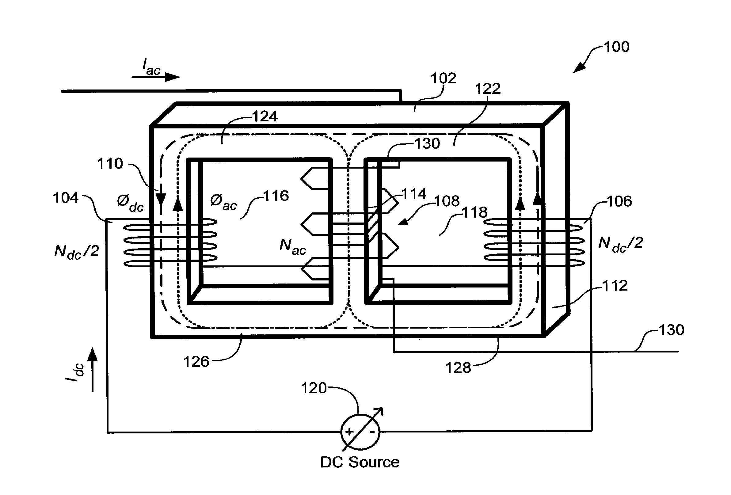
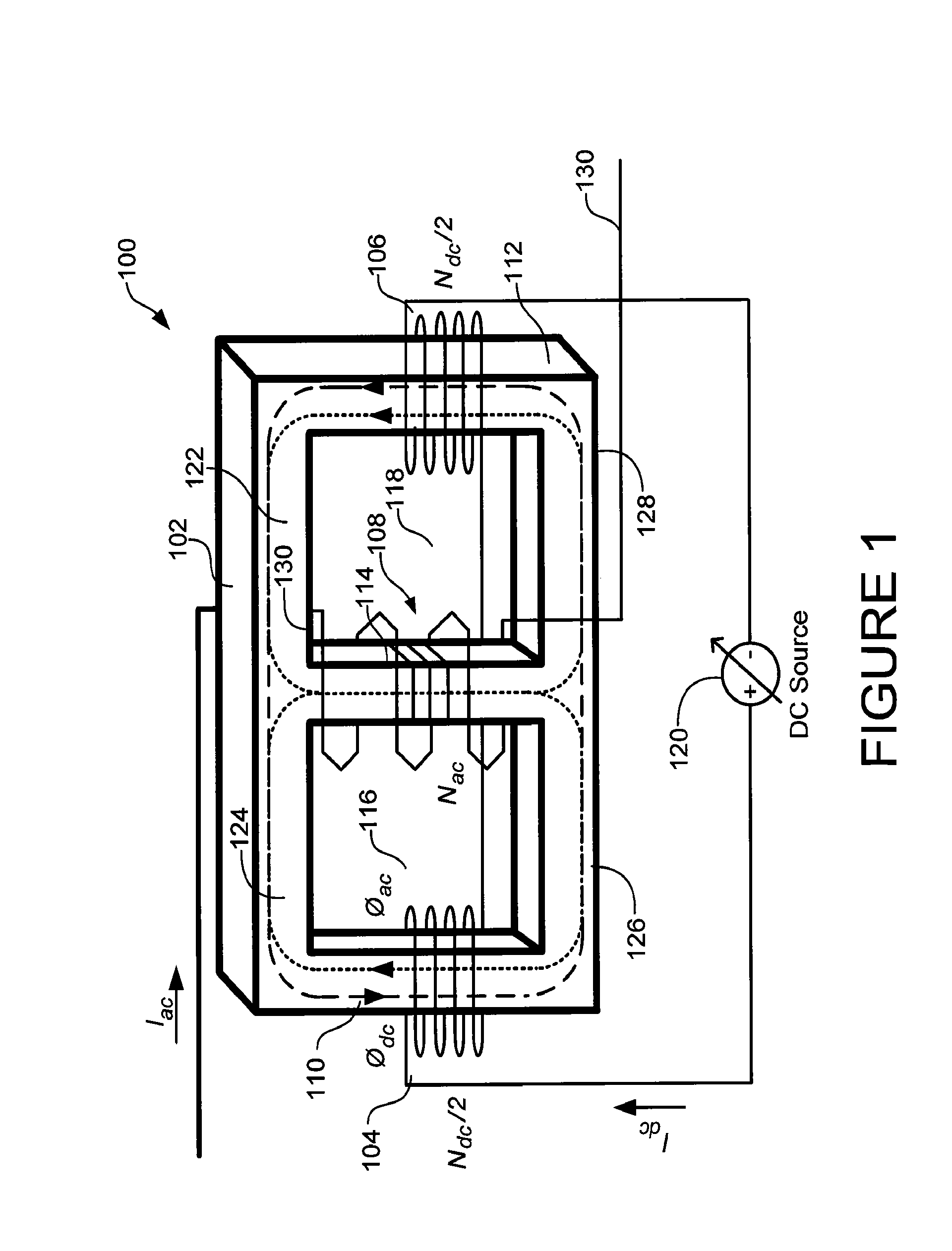
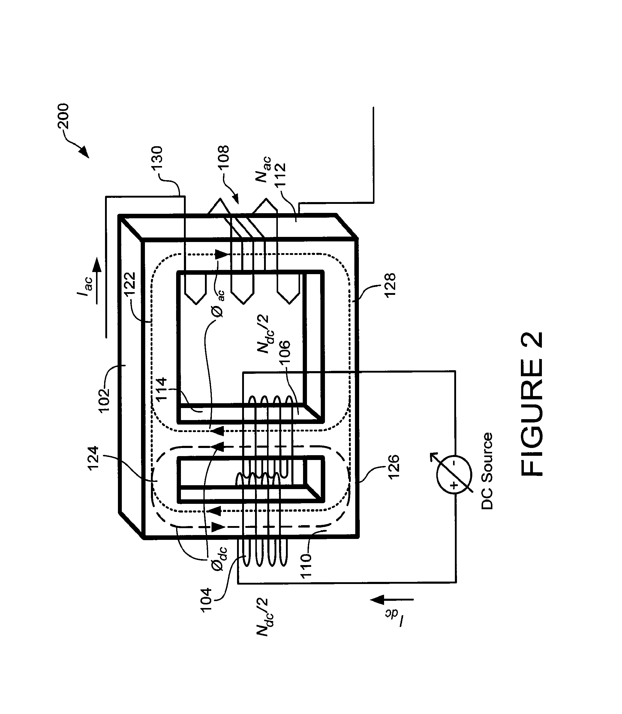
[0019]A magnetic amplifier may include a core that provides a controllable reluctance for magnetic flux, a power winding, which receives energy from an alternating current (“ac”) source and delivers alternating load current to load and two or more separate control windings coupled in series that receive power from a geographically local source that may be power system dependent or independent. The control windings are configured in such a way that the bias magnetic flux generated by the control current (e.g., ac or direct current “dc”) flowing through the control winding does not flow through the power windings and gaps that may be positioned in the core. The layout and phasing of the control windings cancel out or limit the voltage induced in the control windings caused by the load current passing through the power windings and limit the control current flux flow to a specified portion of the core. The placement of the control windings and gaps positioned in the core confine the sa...


PUM


Abstract

A magnetic amplifier includes a saturable core having a plurality of legs. Control windings wound around separate legs are spaced apart from each other and connected in series in an anti-symmetric relation. The control windings are configured in such a way that a biasing magnetic flux arising from a control current flowing through one of the plurality of control windings is substantially equal to the biasing magnetic flux flowing into a second of the plurality of control windings. The flow of the control current through each of the plurality of control windings changes the reactance of the saturable core reactor by driving those portions of the saturable core that convey the biasing magnetic flux in the saturable core into saturation. The phasing of the control winding limits a voltage induced in the plurality of control windings caused by a magnetic flux passing around a portion of the saturable core.

Description

RELATED APPLICATION[0001]This application claims the benefit of priority of U.S. Provisional Pat. App. No. 61 / 446,515 filed Feb. 25, 2011 and titled “Power Flow Control Using Distributed Saturable Reactors,” which is incorporated by reference.STATEMENT REGARDING FEDERALLY SPONSORED RESEARCH AND DEVELOPMENT[0002]This application was made with United States government support under Contract No. DE-AC05-00OR22725 awarded by the United States Department of Energy. The United States government has certain rights in these inventions.BACKGROUND[0003]1. Technical Field[0004]This application relates to devices in which electrical signals control the flow of electrical power and, more particularly, to devices that control reactance through the application of a control current.[0005]2. Related Art[0006]Some saturable reactors control current flow through changing reluctance (magnetic resistance). The core of these reactors may be magnetically saturated in which the magnetic domains of the core...

Claims


Application Information

Patent Timeline
IPC IPC(8): G05F1/32H03F9/02
CPCG05F1/32H03F9/02
Inventor DIMITROVSKI, ALEKSANDAR D.
Owner UT BATTELLE LLC
Why Eureka
Try Eureka