Eureka AIR delivers breakthrough ideas for toughest innovation challenges, trusted by R&D personnel around the world.

Method for Determining Target Optical Functions

Active Publication Date: 2013-12-12
ESSILOR INT CIE GEN DOPTIQUE
View PDF4 Cites 9 Cited by
  • Summary
  • Abstract
  • Description
  • Claims
  • Application Information

AI Technical Summary

Benefits of technology

The invention aims to improve the comfort of wearing ophthalmic lenses to maximize binocular performance. The method includes selecting an initial pair of lenses and determining target optical functions. A current pair of lenses is then defined with associated optical functions, and the difference between the current and target optical functions is minimized with a cost function.

Problems solved by technology

For presbyopic wearers, the value of the power correction is different for far vision and near vision, due to the difficulties of accommodation in near vision.
This use is not strictly correct in so far as a target optical function has only a sense for a wearer—ophthalmic lens and ergorama system.
Indeed, the more criteria considered, the more the lens obtained is likely to satisfy the wearer's needs.
However, increasing the number N of criteria may result in increasing the time taken for calculation.
In some cases, even though the ophthalmic lens is optimized, the optical function of the optimized ophthalmic lens may not reach the target optical function.
In some case, the optical function of the optimized ophthalmic lens may have optical characteristic worse than if the ophthalmic lens had not been optimized.

Method used


Image

  • Method for Determining Target Optical Functions
  • Method for Determining Target Optical Functions
  • Method for Determining Target Optical Functions

Examples


example 1

Prior Art

[0179]Example 1 corresponds to an example according to prior art. In this case, the power prescription in far vision is 1.0 δ for the right eye and 3.0δ for the left eye. Further, the addition prescribed is 2.75 δ for each eye. For this example 1, no astigmatism is prescribed for the wearer.

[0180]FIGS. 19, 20 and 21 are the superimposed figures obtained for the target optical functions obtained by a method according to the prior art. For clarity, the target optical function of the left eye is represented taking into account the symmetry between both eye relative to the line joining the two eye rotation centers of the wearer and passing, for instance, through the middle of the segment joining the two eye rotation centers. In the map which is represented:

αleft—map=αleft

βleft—map=−βleft [0181]wherein (αleft,βleft) is the given gaze direction of the left eye and (αleft—map, βleft—map) is the corresponding gaze direction in the right eye frame

[0182]For clarity, the correspondin...

example 2

[0184]Example 2 corresponds to the same example of prescription considered for example 1. Thus, the power prescription in far vision is 1.0 δ for the right eye and 3.0 δ for the left eye; the addition prescribed is 2.75 δ for each eye and no astigmatism is prescribed to the wearer.

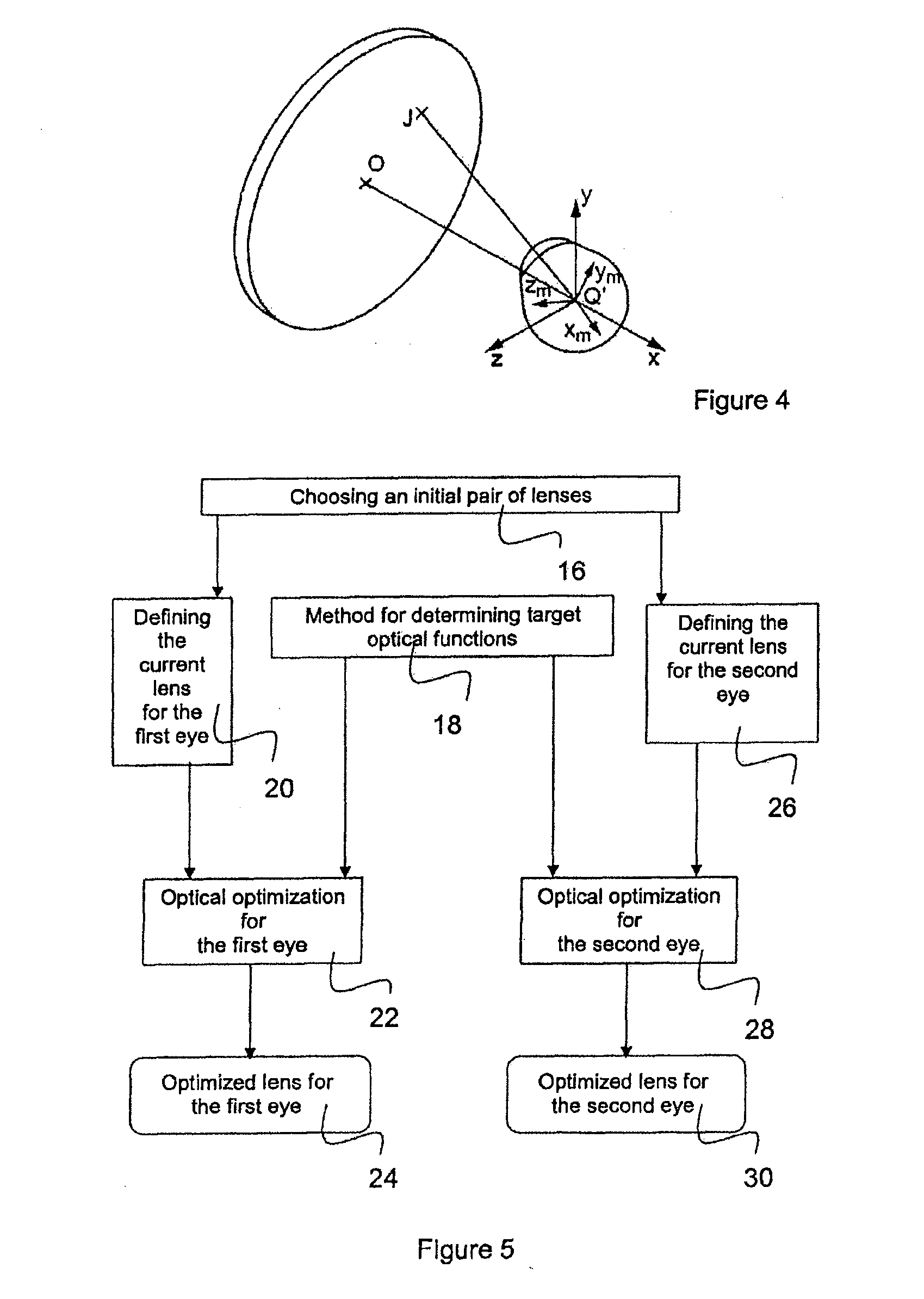
[0185]Example 2 corresponds to the results obtained when carrying out the method for determining target optical functions according to the flowchart of FIG. 10. In this case, the first eye is the right eye and the second eye is the left eye.

[0186]The data relating to the right eye which are considered at step 32 are the prescription for a power, an addition and for astigmatism. These data are used to generate a first intermediate target optical function for the right eye OFi1. This corresponds to the step 62 of the flowchart according to the method of FIG. 10. The characteristics of this target optical function are shown on FIGS. 31, 32 and 33.

[0187]Based on this optical function OFi1, it is possible to ge...

example 3

[0192]Example 3 corresponds to the same example of prescription considered for examples 1 or 2. Thus, the power prescription is 1.0 δ for the right eye and 3.0 δ for the left eye; the addition prescribed is 2.75 δ for each eye and no astigmatism is prescribed to the wearer. Furthermore, the right eye is considered as the main eye. To improve the performance of the pair of lenses, the data relative to the main eye will be have more importance in the definition of the two target optical functions.

[0193]Accordingly, example 3 corresponds to the results obtained when carrying out the method for determining target optical functions according to the flowchart of FIG. 12. In this case, the first eye is the right eye and the second eye is the left eye.

[0194]The data relating to the right eye which are considered at step 32 are the prescription for a power, an addition and for astigmatism. These data are used to generate a target optical function for the right eye OFT1. This corresponds to t...


PUM


Abstract

A method for determining target optical functions for a pair of ophthalmic lenses is provided, the method comprising steps of: generating a first target optical function (OFT1) for a first lens of the pair based at least on data relating to a first eye, generating a second target optical function (OFT2) for a second lens of the pair based at least on data relating to the first eye. This method makes it possible to obtain optical functions having improved symmetry. Thus, when using the target optical functions in an optical optimization method, lenses with improved binocular properties can be obtained. The comfort of the wearer of the pair of lenses is thus improved.

Description

RELATED APPLICATIONS[0001]This is a U.S. National Phase application under 35 USC §371 of international application PCT / EP2012 / 052788, filed on Feb. 17, 2012.[0002]This application claims the priority of European patent application no. 11305175.9 filed Feb. 18, 2011, the entire content of which is hereby incorporated by reference.FIELD OF THE INVENTION[0003]The invention relates to a method for determining target optical functions for a pair of ophthalmic lenses. The invention further relates to a method of optical optimization of a pair of ophthalmic lenses, a method for manufacturing a pair of ophthalmic lenses, a set of apparatuses for manufacturing a pair of ophthalmic lenses, a set of data, a computer program product and a computer readable medium associated to this method.BACKGROUND OF THE INVENTION[0004]A wearer may be prescribed a positive or negative optical power correction. For presbyopic wearers, the value of the power correction is different for far vision and near visio...

Claims


Application Information

Patent Timeline
IPC IPC(8): G02C7/02
CPCG02C7/028G02C7/025G02C7/027G02C7/061G02C7/02G02C7/06
Inventor CONTET, AUDEDE ROSSI, HELENE
Owner ESSILOR INT CIE GEN DOPTIQUE
Why Eureka
Eureka Blog
Learn More