Apparatus for Infusing Fluid

a technology for infusing fluid and apparatus, which is applied in the direction of positive displacement liquid engines, process and machine control, instruments, etc., can solve the problem of door becoming unlatched from the housing

Active Publication Date: 2013-12-19
DEKA PROD LLP
View PDF7 Cites 266 Cited by
  • Summary
  • Abstract
  • Description
  • Claims
  • Application Information

AI Technical Summary

Benefits of technology

[0193]In some embodiments, the parameter of the tube is determined using a birefringence effect.
[0194]The parameter of the tube may be an identification of a particle disposed within the tube, an identification of a liquid disposed within the tube, a determined material of the tube, a volume of fluid within the tube along a predetermined portion of the tube, an identification of a bubble within a liquid disposed within the tube, and / or whether the tube is present on the tube platen. The parameter of the tube may be used to calibrate a control system of the pump.
[0195]The processor and the image sensor may be configured to estimate the parameter using a color spectrum of the light affected by a birefringence effect. The processor and the image sensor may be configured to estimate the parameter using a moiré pattern of the light affected by a birefringence effect.

Problems solved by technology

Despite the existence of systems intended to facilitate the care process, such as those incorporating electronic medical records (“EMR”) and computerized provider order entry (“CPOE”), the process of providing comprehensive care to patients including ordering and delivering medical treatments, such as medications, is associated with a number of non-trivial issues.
The door may become unlatched from the housing after a substantial amount of actuation of the lever handle away from the door.

Method used


Image

  • Apparatus for Infusing Fluid
  • Apparatus for Infusing Fluid
  • Apparatus for Infusing Fluid

Examples


Embodiment Construction

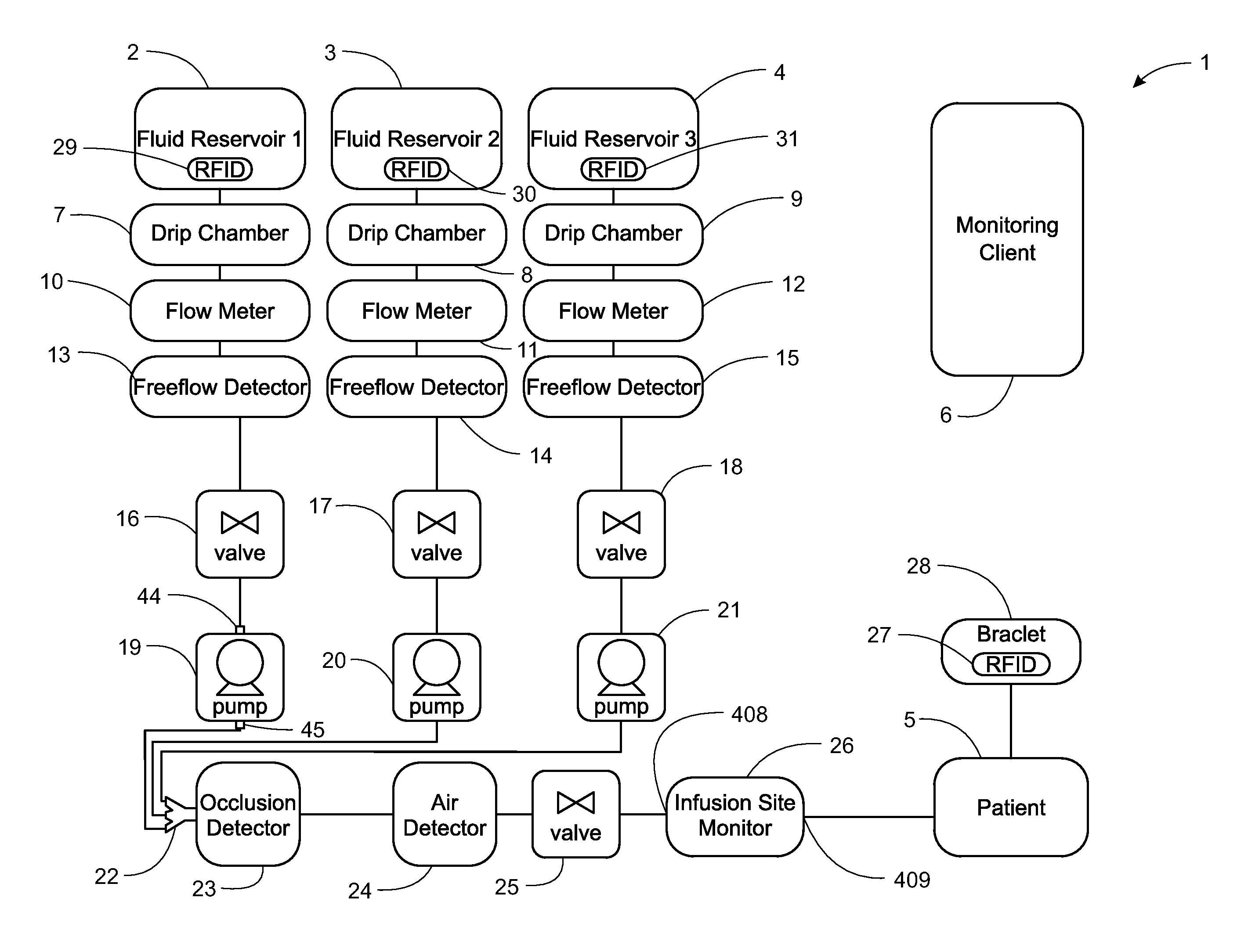
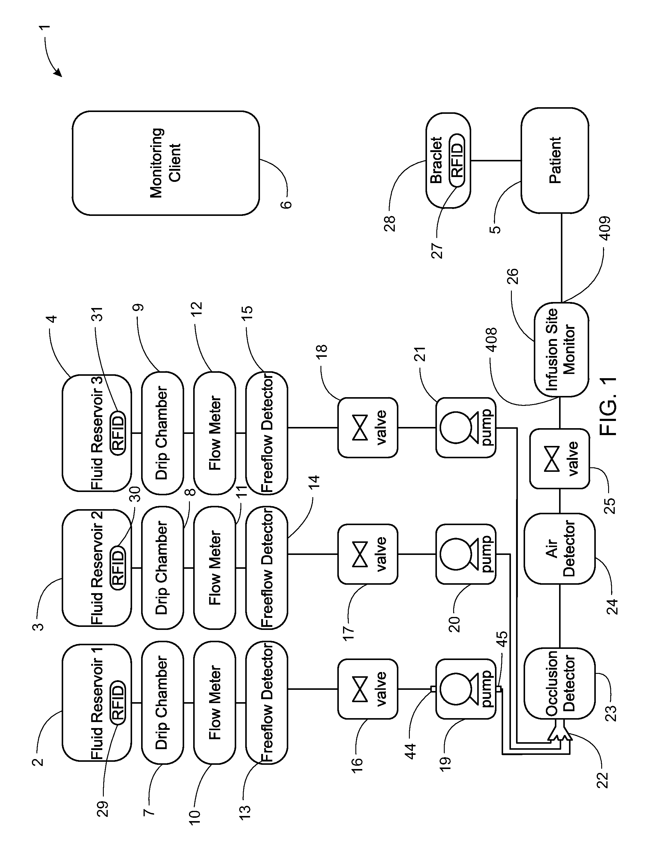
[0466]FIG. 1 shows a block diagram of a system 1 for infusing fluid. System 1 includes fluid reservoirs 2, 3, and 4 for infusing the fluid contained therein into a patient 5. The fluid reservoirs 2, 3, and 4 are gravity fed into drip chambers 7, 8, and 9, respectively. The drip chambers 7, 8, and 8 are respectively fed into flow meters 10, 11, and 12. From the flow meters 10, 11, and 12, the fluid is fed into free-flow detectors 13, 14, and 15, respectively.

[0467]System 1 also includes valves 16, 17, and 18 from a respective free-flow detector of the free-flow detectors 13, 14, and 15. Pumps 19, 20, and 21 receive fluid from valves 16, 17, and 18, and combine the fluid using a connector 22. The valves 16, 17, and 18 may be in wireless or wired communication with a respective pump 19, 20, and 21 to control the flow rate and / or discharge profile. For example, the pump 19 may communicate wirelessly with the valve 16 to adjust the opening and closing of the valve 16 to achieve a target ...


PUM


Abstract

A pump for pumping fluid includes a tube platen, a plunger, a bias member, inlet and outlet valves, an actuator mechanism, a position sensor, and a processor. The plunger is configured for actuation toward and away from the infusion-tube when the tube platen is disposed opposite to the plunger. The tube platen can hold an intravenous infusion tube. The bias member is configured to urge the plunger toward the tube platen.

Description

CROSS REFERENCE TO RELATED APPLICATIONS[0001]The present application is a Non-Provisional Application which claims priority to and the benefit of the following:[0002]U.S. Provisional Patent Application Ser. No. 61 / 679,117, filed Aug. 3, 2012 and entitled System, Method, and Apparatus for Monitoring, Regulating, or Controlling Fluid Flow (Attorney Docket No. J30); and[0003]U.S. Provisional Patent Application Ser. No. 61 / 651,322, filed May 24, 2012 and entitled System, Method, and Apparatus for Electronic Patient Care (Attorney Docket No. J46), both of which are hereby incorporated herein by reference in their entireties.[0004]This application claims priority to and is also a Continuation-In-Part Application of the following:[0005]U.S. patent application Ser. No. 13 / 333,574, filed Dec. 21, 2011 and entitled System, Method, and Apparatus for Electronic Patient Care, now U.S. Publication No. US-2012-0185267-A1, published Jul. 19, 2012 (Attorney Docket No. 197), and[0006]PCT Application ...

Claims


Application Information

Patent Timeline
Patent Type & Authority Applications(United States)
IPC IPC(8): A61M5/168
CPCA61M5/16859A61M5/1411A61M2205/18A61M5/14228A61M5/1415A61M5/1417A61M5/14216A61M5/1452A61M5/1456A61M5/1458A61M5/16827A61M5/16831A61M5/1689A61M2005/16863A61M2005/16868A61M2205/12A61M2205/14A61M2205/3306A61M2205/3317A61M2205/332A61M2205/3375A61M2205/3576A61M2205/50A61M2205/505A61M2205/52A61M2209/082A61M2209/086A61M5/14224G16H40/67G16H20/17F04B43/08F04B43/082F04B43/1223
Inventor KAMEN, DEANKERWIN, JOHN M.MURPHY, COLIN H.PARKER, JONATHANPAWLOWSKI, DANIEL F.VAN DER MERWE, DIRK A.GRAY, LARRY B.LANGENFELD, CHRISTOPHER C.PLACE, MICHAEL S.SLATE, MICHAEL J.
Owner DEKA PROD LLP
Why Eureka
Try Eureka