Broadcasting device, communication terminal, and broadcasting system

a technology of broadcasting device and communication terminal, which is applied in the direction of measurement device, beacon system, instruments, etc., can solve the problems of frequent inaccuracy, gps radio signals cannot reach communication terminals located in indoor spaces, and obtain positional information

Inactive Publication Date: 2013-12-26
RICOH KK
View PDF2 Cites 21 Cited by
  • Summary
  • Abstract
  • Description
  • Claims
  • Application Information

AI Technical Summary

Problems solved by technology

One problem with the GPS is that GPS radio signals can hardly reach communication terminals located in an indoor space (or area).
However, the positional information is obtained by the differential positioning with frequent inaccuracies.
However, since a signal from an IMES transmitter is transmitted to a predetermined area, the absolute positional information may have a margin of error.
With the related-art method, however, the communication device can not accurately determine which one of the positional information either obtained by PDR or obtained by IMES indicates a more precise current position.

Method used


Image

  • Broadcasting device, communication terminal, and broadcasting system
  • Broadcasting device, communication terminal, and broadcasting system
  • Broadcasting device, communication terminal, and broadcasting system

Examples


Embodiment Construction

[0052]In the following, embodiments of the present invention will be described with reference to the accompanying drawings.

[0053]Preferred embodiments of the present invention are described below with reference to FIGS. 1 through 25.

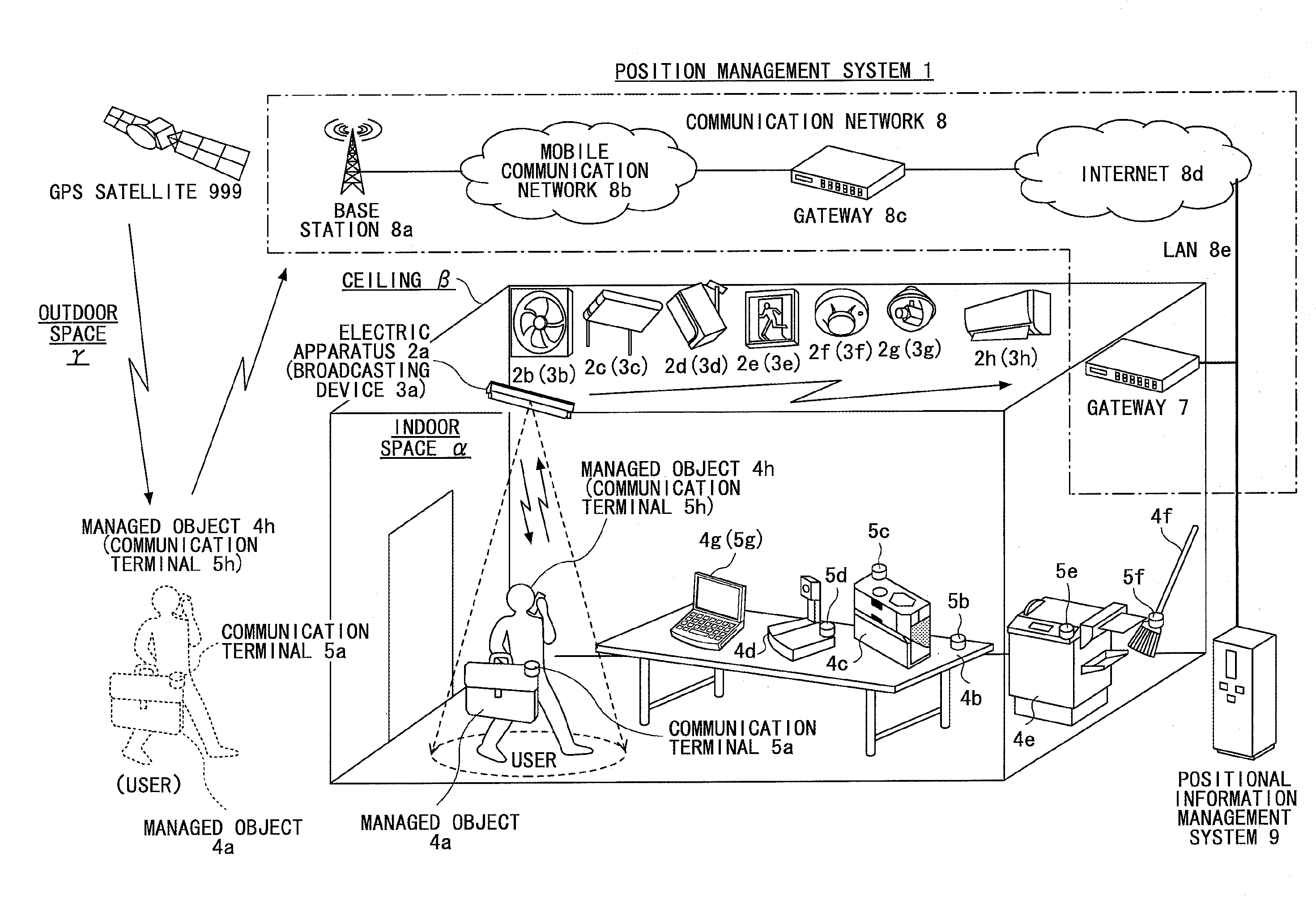
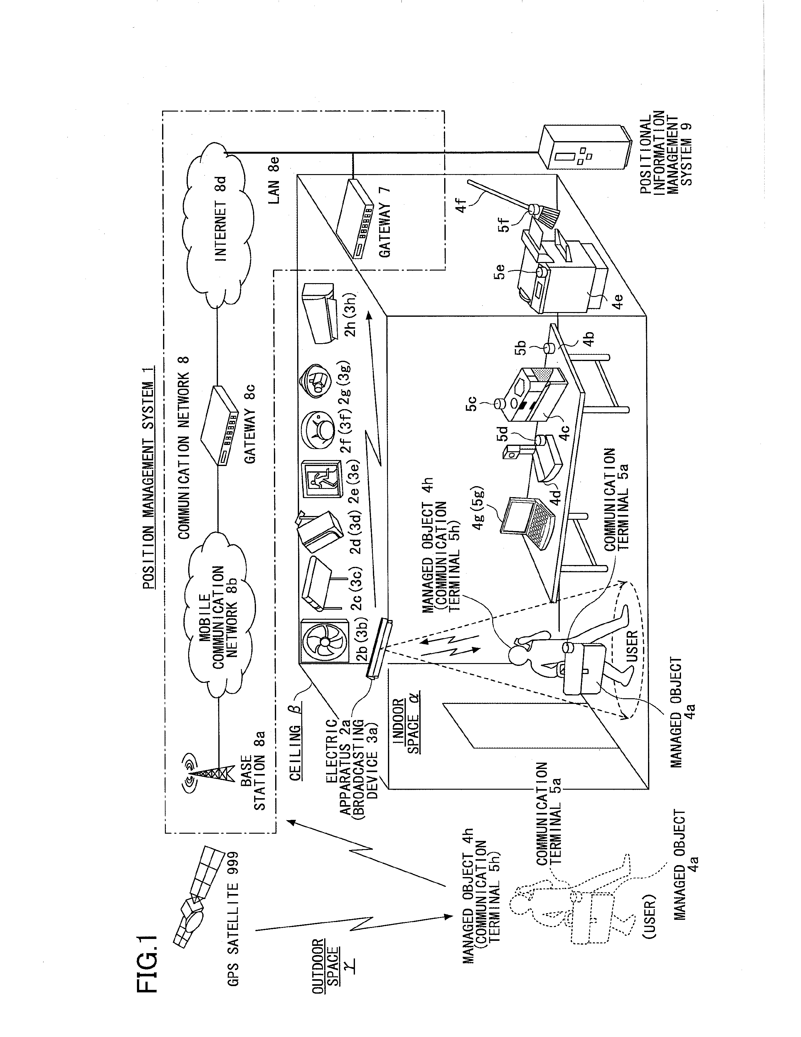
[0054]An outline of a position management system according to an embodiment is described below with reference to FIG. 1. FIG. 1 is a drawing illustrating an exemplary configuration of a position management system 1 according to the present embodiment.

[0055]As illustrated in FIG. 1, the position management system 1 includes plural broadcasting devices 3a, 3b, 3c, 3d, 3e, 3f, 3g, and 3h provided on or near a ceiling β of an indoor space (or area) α, plural communication terminals 5a, 5b, 5c, 5d, 5e, 5f, 5g, and 5h on or near a floor of the indoor space α, and a positional information management system 9.

[0056]Each of the broadcasting devices 3a, 3b, 3c, 3d, 3e, 3f, 3g, and 3h stores positional information Xa, Xb, Xc, Xd, Xe, Xf, Xg, or Xh indicating a posi...


PUM


Abstract

A broadcasting device includes a broadcasting unit configured to broadcast positional information indicating an indoor position of the broadcasting device to a predetermined area, wherein the broadcasting unit broadcasts range information indicating the size of the predetermined area together with the positional information.

Description

CROSS-REFERENCE TO RELATED APPLICATIONS[0001]The present application is based upon and claims the benefit of priority of Japanese Patent Application No. 2012-138694 filed on Jun. 20, 2012, and Japanese Patent Application No. 2012-229877 filed on Oct. 17, 2012, the entire contents of which are incorporated herein by reference.BACKGROUND OF THE INVENTION[0002]1. Field of the Invention[0003]An aspect of this disclosure is related to a technology for delivering positional information.[0004]2. Description of the Related Art[0005]There exists technology for determining positions of communication terminals of users using a global positioning system (GPS). In the GPS, about 30 GPS satellites orbiting the Earth transmit radio signals indicating time. A communication terminal on the Earth including a GPS receiver receives radio signals from some of the GPS satellites and calculates the distance between the communication terminal and the GPS satellites based on differences between the time the...

Claims


Application Information

Patent Timeline
Patent Type & Authority Applications(United States)
IPC IPC(8): G01S1/02
CPCG01S1/02G01S1/68
Inventor FUKUDA, MICHITAKAMATSUSHITA, YUSUKEKUSAKARI, SHINMIYAUCHI, KUNIHIROOHASHI, YASUOKOKUBO, ATSUSHIAOKI, SHINJIHIROI, TAKAAKIMIYAWAKI, SEIJIKAWASAKI, SATOSHI
Owner RICOH KK
Why Eureka
Try Eureka