Image reading device and recording device

a reading device and a recording device technology, applied in the field of image reading devices, can solve the problems of wasting space under the inverting path, and achieve the effects of reducing the size of the entire machine, and reducing a wasted spa

Active Publication Date: 2013-12-26
SEIKO EPSON CORP
View PDF4 Cites 5 Cited by
  • Summary
  • Abstract
  • Description
  • Claims
  • Application Information

AI Technical Summary

Benefits of technology

This patent is about an improved image reading device that reduces wasted space and a recording device that can be used in combination with it. The device includes a transparent plate with a placement area for an original document, and a reading unit that can read an image from the other side of the plate. There is also an original document transport device that can be moved between a closed position to cover the plate and an open position. The transport device has an inverting path to transport the original document with its front and back sides inverted. This frees up space below the inverting path and allows it to act as a standby position for the reading unit. By using this standby position, the device can reduce wasted space and make the machine smaller. Another version of the device defines a white reference above a standby position to further reduce wasted space.

Problems solved by technology

Therefore, in the image reading device, the area below the inverting path has been a wasted space.

Method used


Image

  • Image reading device and recording device
  • Image reading device and recording device
  • Image reading device and recording device

Examples


Embodiment Construction

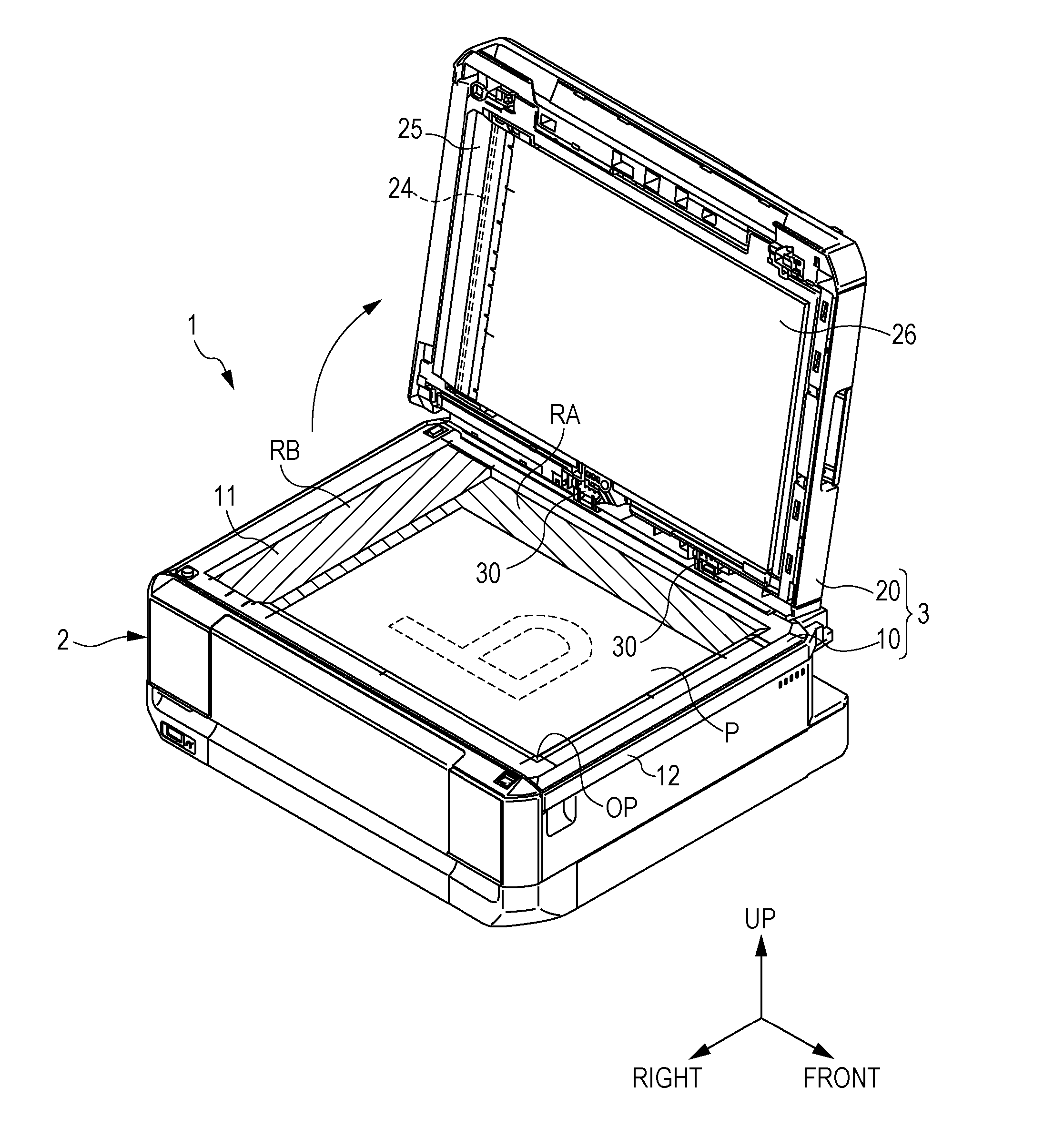
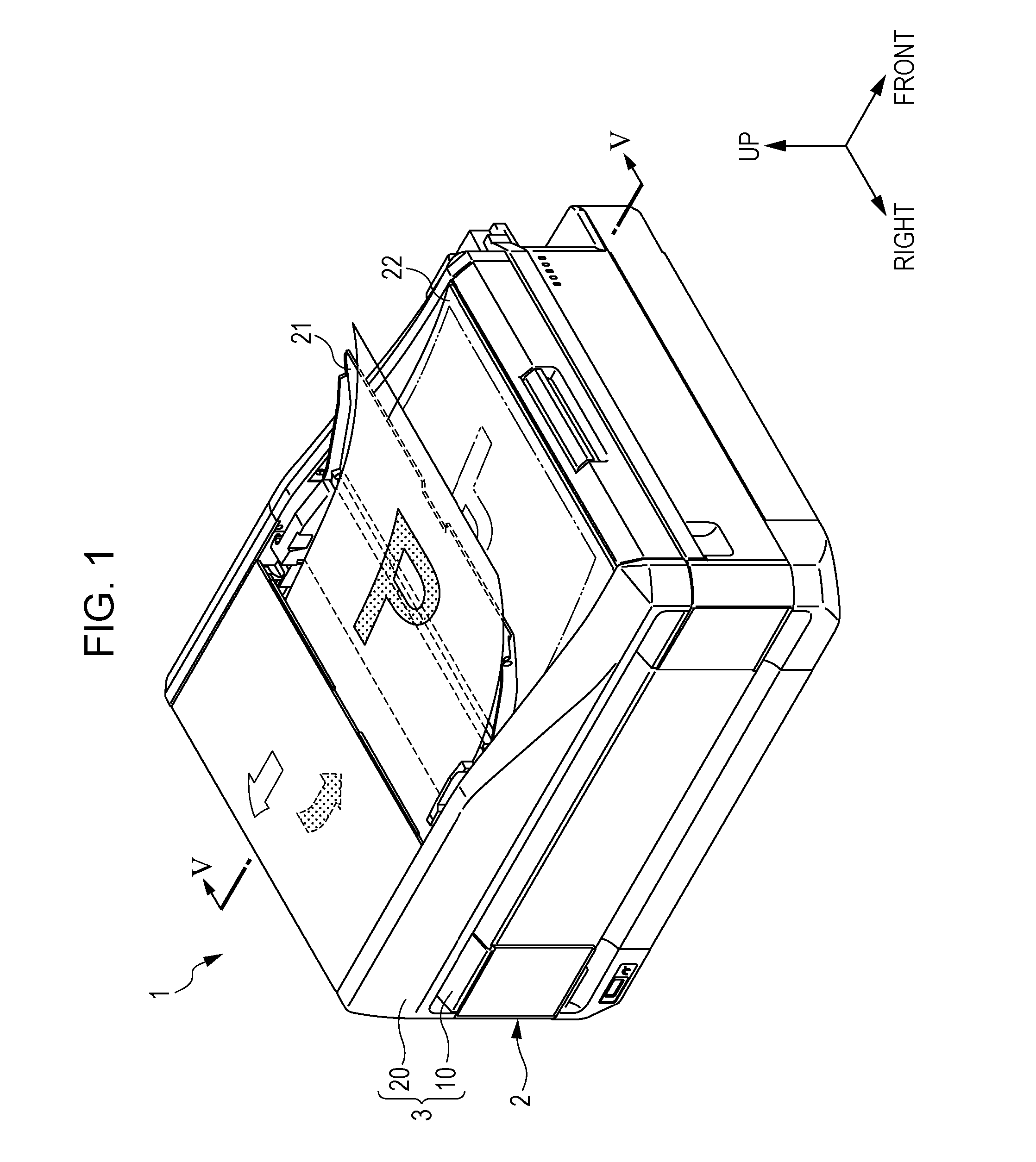
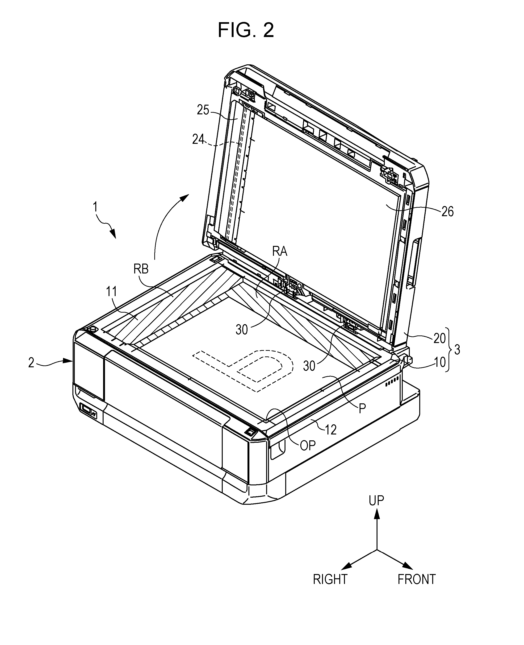
[0028]Hereinafter, with reference to the drawings, the entire configuration of a multi-functional device 1 of the present embodiment will be described. In the following description, the “front-rear direction,” the “left-right direction” and the “up-down direction” are indicated by arrows pointing in their respective directions in the drawings.

[0029]As illustrated in FIG. 1, a multifunction machine 1 includes an image formation device (i.e., a recording device) 2 and an image reading device 3. The image formation device 2 includes a recording unit, such as a recording head, which performs printing of characters and printing of images, by injecting ink, on a sheet of printing paper as an example of a medium. The image reading device 3 is disposed above the image formation device 2 and is configured to read an image of an original document P. The image reading device 3 includes, as main components thereof, a document reading device 10 and an original document transport device (hereafte...


PUM


Abstract

An image reading device includes a transparent plate and a CIS. The transparent plate has a placement area in which an original document is placed and a transport area which corresponds to a transport position of the original document by a transport device. The CIS reads an image of the original document via the transparent plate. The transport device includes an inverting path at a position on the transparent plate opposite to the placement area seen from the transport area. On a second surface side of the transparent plate, the CIS is moved among a first reading area which corresponds to the placement area of the transparent plate, a second reading area which corresponds to the transport area of the transparent plate, and a standby position defined below the inverting path of the transport device.

Description

BACKGROUND[0001]1. Technical Field[0002]The present invention relates to an image reading device which includes a movable reading unit configured to read an image of an original document. The present invention also relates to a recording device used in combination with the image reading device.[0003]2. Related Art[0004]As an exemplary recording device which may be used in combination with such an image reading device, a multi-functional device described in JP-A-2010-41481 has been proposed. An image reading device of this multi-functional device includes a transparent plate on which, on the side of a first surface thereof, an original document may be placed and includes a reading unit configured to read an image of the original document while moving, on the side of a second surface of the transparent plate, in parallel with the transparent plate. On the image reading device, an original document transport device is disposed to cover the entire first surface of the transparent plate....

Claims


Application Information

Patent Timeline
Patent Type & Authority Applications(United States)
IPC IPC(8): H04N1/04H04N1/10
CPCH04N1/0461H04N1/1061H04N1/1039H04N1/00578H04N1/0058H04N1/0464H04N1/1017H04N1/12H04N1/193
Inventor SHIMAZU, MASAMITSUMIYAMOTO, SHINTARO
Owner SEIKO EPSON CORP
Why Eureka
Try Eureka