Electricity storage device

A power storage device and power collection technology, applied in the direction of batteries, circuits, electrical components, etc., can solve the problems of increasing space and increasing wasted space, and achieve the effects of reducing wasted space, suppressing failures, and improving output density

Inactive Publication Date: 2014-12-17
TOYOTA IND CORP
View PDF5 Cites 6 Cited by
  • Summary
  • Abstract
  • Description
  • Claims
  • Application Information

AI Technical Summary

Problems solved by technology

As a result, in the direction perpendicular to the lamination direction of the electrode assembly 84 in the case 80a, the space for the uncoated portion 81b and the current collector group 81c becomes large, and the performance of the secondary battery 80 will increase. Useless waste of space

Method used


Image

  • Electricity storage device
  • Electricity storage device
  • Electricity storage device

Examples


no. 1 approach

[0068] Below, combine Figure 1A ~ Figure 7 A first embodiment in which the present invention is embodied in a secondary battery mounted on a vehicle (for example, an industrial vehicle or a passenger vehicle) will be described. In addition, secondary batteries are used to drive travel motors.

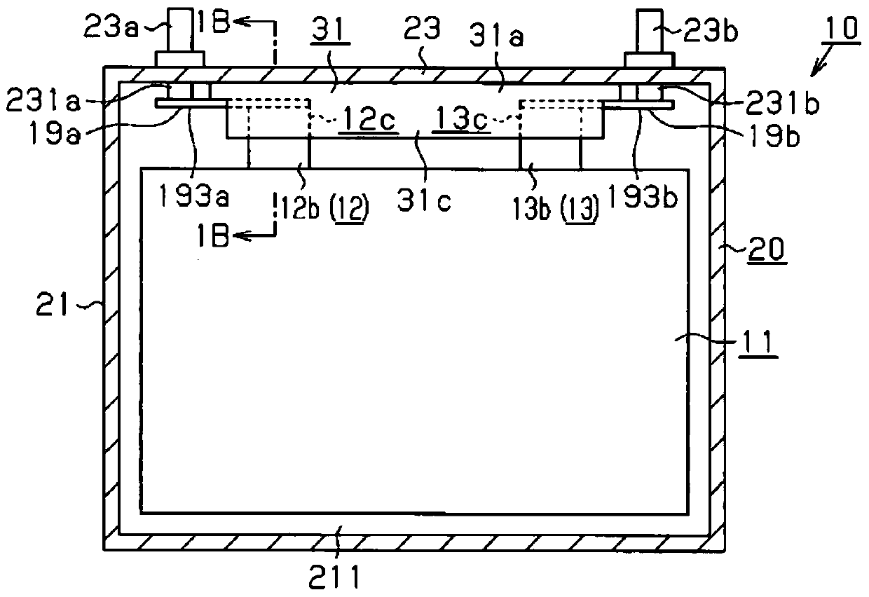
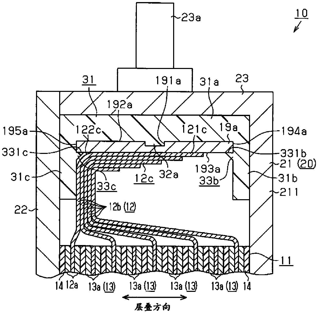
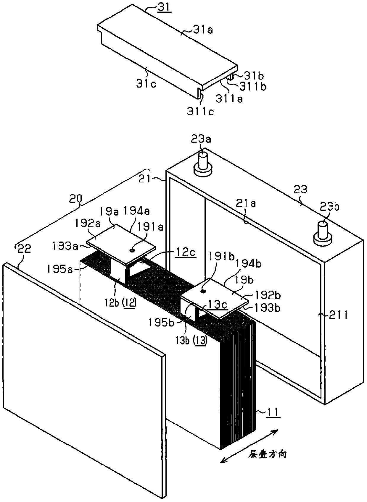
[0069] Such as Figure 1A As shown, the secondary battery 10 is composed of an electrode assembly 11 and an aluminum case 20 that accommodates the electrode assembly 11 . Such as figure 2 As shown, the case 20 is composed of a bottomed rectangular box-shaped case body 21 with an insertion portion 21a capable of being inserted into the electrode assembly 11 formed on one surface, and a rectangular plate-shaped case body 21 that closes the insertion portion 21a of the case body 21. Cover 22 constitutes. An electrolytic solution is injected into the case 20 . Terminal wall 23 (the wall of housing 20 ), which is one of four side walls standing upright from the periphery of bottom wal...

no. 2 approach

[0095] Below, combine Figure 8A ~ Figure 11 , a second embodiment in which the present invention is embodied as a secondary battery mounted on a vehicle (for example, an industrial vehicle or a passenger vehicle) is performed. In addition, in the embodiment described below, the same reference numerals and the like are attached to the same structures as those of the first embodiment already described, and overlapping description thereof will be omitted or simplified.

[0096] Such as Figure 8A As shown in FIG. 8B , a U-shaped insulating member 91 is disposed between the positive electrode current collecting member 19 a and the case 20 and between the negative electrode current collecting member 19 b and the case 20 . The insulating member 91 has a rectangular plate-shaped first insulating portion 91a extending along the second ends 195a, 195b of the positive electrode current collecting member 19a and the negative electrode current collecting member 19b. In addition, the in...


PUM


Abstract

A positive electrode collector member and a negative electrode collector member are disposed so that the connection surfaces of the positive electrode collector member and the negative electrode collector member, which are connected to collector groups, face an electrode assembly body. Inside a case, an insulating member is disposed between the positive electrode collector member and the terminal wall of the case and between the negative electrode collector member and the terminal wall of the case and separates the facing surfaces and the terminal wall from each other. As a result, it is possible to reduce wasted space and to isolate the collector members and the collector groups from the case.

Description

technical field [0001] The present invention relates to an electricity storage device including an electrode assembly. Background technique [0002] A secondary battery as a type of power storage device such as Figure 24 As shown, there is provided an electrode assembly 84 in which a strip-shaped separator 83 is interposed between a strip-shaped positive electrode 81 and a strip-shaped negative electrode 82 and wound in a spiral shape. Specifically, the positive electrode 81 has an active material layer 81 a coated with an active material, and an uncoated portion 81 b (current collector portion) not coated with an active material. In addition, the negative electrode 82 has an active material layer 82 a coated with an active material, and an uncoated portion (current collector portion) not coated with an active material. In addition, in Figure 24 In , the illustration of the uncoated portion of the negative electrode 82 is omitted for convenience of description. [0003] ...

Claims


Application Information

Patent Timeline
Patent Type & Authority Applications(China)
IPC IPC(8): H01M2/34H01M2/26H01M10/04H01M50/528H01M50/119H01M50/533H01M50/54
CPCH01M10/0413H01M10/0463H01M10/0404H01M10/0583H01M10/0585H01M2220/20H01M50/528H01M50/54H01M50/119H01M50/533Y02E60/10H01M50/15Y02P70/50
Inventor 奥田元章南形厚志滨口阳平
Owner TOYOTA IND CORP
Why Eureka
Try Eureka