Vehicular lamp and window unit

a technology of vehicle lamps and window units, applied in the field of lamps, can solve the problems of reducing the visible region behind the vehicle, causing leakage of light, and wrongly recognizing the front of the vehicle as the rear of the vehicle, so as to reduce the size of the structure, and reduce the number of parts

Inactive Publication Date: 2014-01-02
KOITO MFG CO LTD
View PDF2 Cites 27 Cited by
  • Summary
  • Abstract
  • Description
  • Claims
  • Application Information

AI Technical Summary

Benefits of technology

[0016]The light-shielding member may be formed on the light guiding member by evaporation. This can reduce the number of parts, and can implement reduction in size of the structure.
[0017]The light guiding member may be molded integrally with the window member. This can also reduce the number of parts, and can implement reduction in size of the structure.
[0018]The window unit may further include an opaque frame member provided on a peripheral edge of the window member, and a part of the light-shielding member may be formed by the frame member. This can also reduce the number of parts, and can implement reduction in size of the structure.

Problems solved by technology

In the above configuration, since a part of the window member is covered by the rear combination lamp mounted thereon, it cannot be avoided that the visible region behind the vehicle is reduced.
Therefore, if the red light reaches the front of the vehicle, those who are around the vehicle may wrongly recognize the front of the vehicle as the rear of the vehicle.
Since light emitted from the light source is internally reflected by the light guiding member, leakage light may be caused at an unexpected location.

Method used


Image

  • Vehicular lamp and window unit
  • Vehicular lamp and window unit
  • Vehicular lamp and window unit

Examples


first embodiment

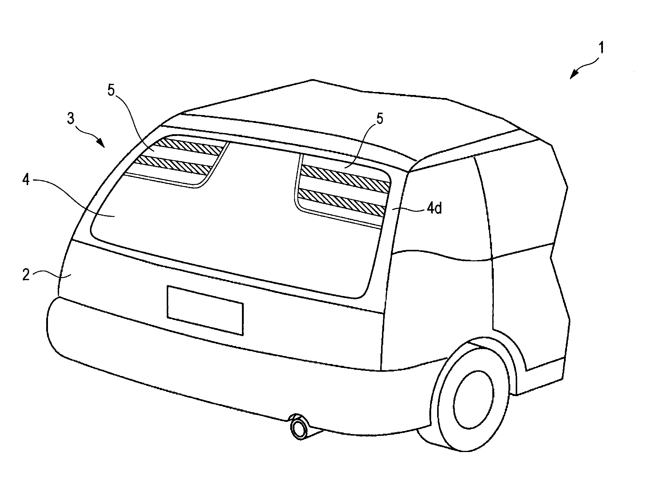
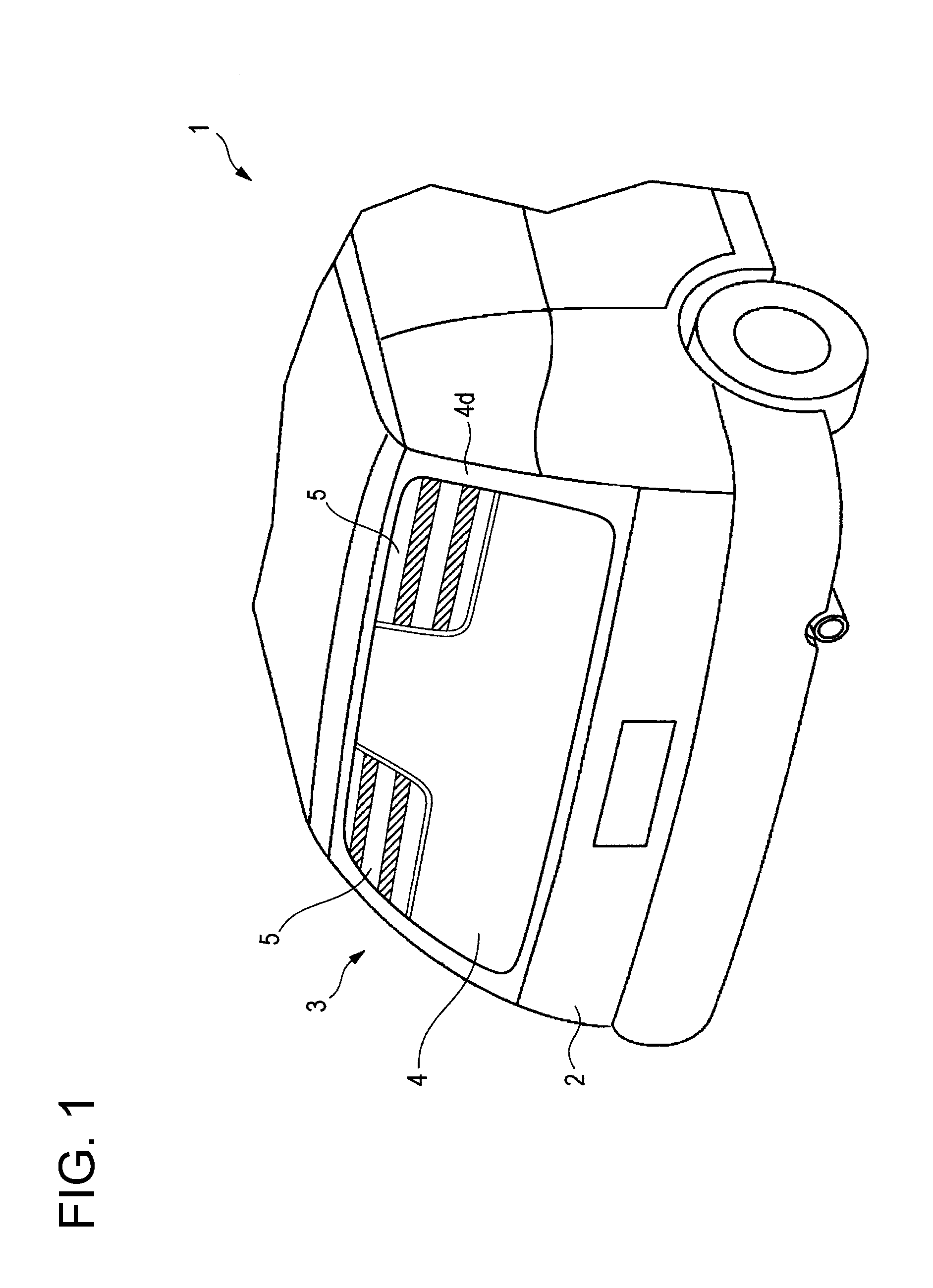
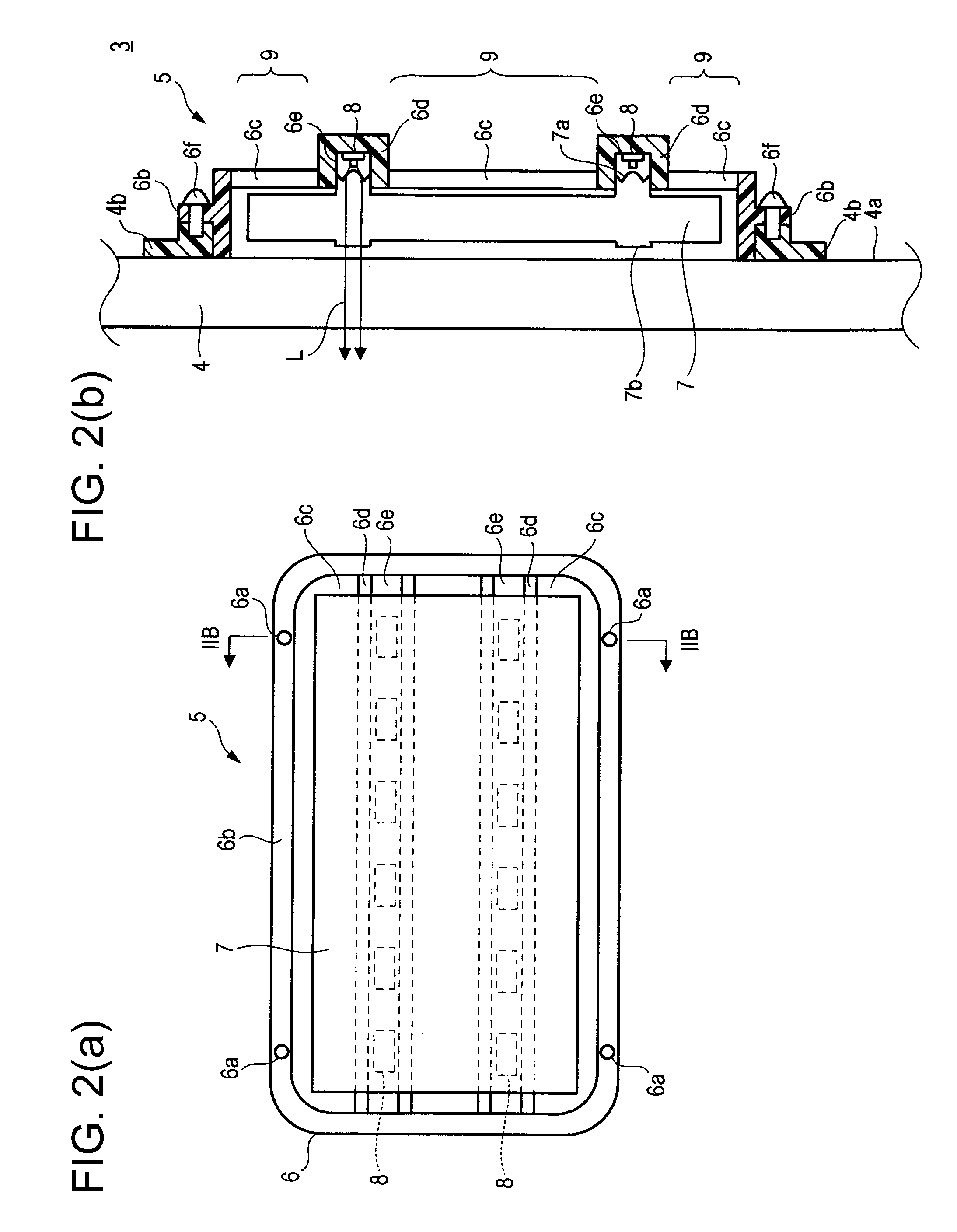
[0035]FIGS. 2(a)-2(b) schematically show the configuration of the lamp 5 according to the present invention. FIG. 2(a) is a front view of the lamp 5 mounted on the vehicle as viewed from the rear, and FIG. 2(b) is a longitudinal sectional view taken along line IIB-IIB in FIG. 2(a). The lamp 5 includes a housing 6, a light guiding member 7, and a plurality of light-emitting diodes (LEDs) 8.

[0036]The housing 6 is a resin member that is formed by integrally molding an opaque frame portion 6b having holes 6a formed therein, a transparent portion 6c, and an opaque portion 6d by two-color molding etc. The opaque portion 6d is provided such that a groove 6e extending in the lateral direction of the vehicle 1 is formed at two positions in the vertical direction of the vehicle 1. The transparent portion 6c is formed in a portion located between the frame portion 6b and each opaque portion 6d.

[0037]The light guiding member 7 is a transparent plate-like member made of a resin such as polymeth...

second embodiment

[0050]FIGS. 4(a)-4(b) schematically show the configuration of a lamp 15 according to the present invention. FIG. 4(a) is a front view of the lamp 5 mounted on a vehicle as viewed from the rear, and FIG. 4(b) is a longitudinal sectional view taken along line IVB-IVB in FIG. 4(a). Those elements which have a similar function to the configuration shown in FIGS. 2(a)-2(b) are denoted with the same reference numerals, and repetitive description thereof will be omitted. The lamp 15 includes a housing 16, a light guiding member 17, and a plurality of LEDs 8.

[0051]The housing 16 is a resin member that is formed by integrally molding an opaque frame portion 16b having holes 16a formed therein, a transparent portion 16c, and an opaque portion 16d by two-color molding etc. The opaque portion 16d is provided at two positions in the vertical direction of the vehicle 1 so as to extend in the lateral direction of the vehicle 1. The transparent portion 16c is formed in a portion located between the...

third embodiment

[0068]FIGS. 6(a)-6(b) schematically show the configuration of a lamp 25 according to the present invention. FIG. 6(a) is a front view of the lamp 25 mounted on a vehicle as viewed from the rear, and FIG. 6(b) is a longitudinal sectional view taken along line VIB-VIB in FIG. 6(a). Those elements which have a similar function to the configuration shown in FIGS. 2(a)-2(b) are denoted with the same reference numerals, and repetitive description thereof will be omitted. The lamp 25 includes a housing 26, a light guiding member 27, and a plurality of LEDs 8.

[0069]The housing 26 is a resin member that is formed by integrally molding an opaque frame portion 26b having holes 26a formed therein, a transparent portion 26c, and an opaque portion 26d by two-color molding etc. The opaque portion 26d is provided at two positions in the vertical direction of the vehicle 1 so as to extend in the lateral direction of the vehicle 1. A groove 26e extending in the lateral direction of the vehicle 1 is f...


PUM


Abstract

A vehicular lamp that is mounted on a vehicle has a light source, a transparent part that is transparent when viewed from inside of a compartment when mounted on the vehicle, a light guiding member that forms at least a part of the transparent part, wherein the light guide member is configured to guide light emitted from the light source toward outside of the compartment when mounted on the vehicle, and a light-shielding member that blocks the light emitted from the light source and that travels toward the inside of the compartment when mounted on the vehicle.

Description

BACKGROUND OF THE DISCLOSURE[0001]1. Field of the Invention[0002]The present invention relates to lamps that are mounted on vehicles, and window units provided on vehicles.[0003]2. Description of the Related Art[0004]A configuration of a window unit is known in which the window unit is formed by integrally mounting a rear combination lamp as a vehicular lamp on a window member (rear windshield) forming a part of a back door that is provided in the rear part of a vehicle and that can be opened and closed (see, e.g., Patent Document 1).[0005][Patent Document 1][0006]Japanese Patent Application Laid-Open (Kokai) No. H06-150704SUMMARY[0007]In the above configuration, since a part of the window member is covered by the rear combination lamp mounted thereon, it cannot be avoided that the visible region behind the vehicle is reduced.[0008]One or more embodiments of the present invention provides a technique of placing a lamp so as to cover a part of a window member while not hindering rear...

Claims


Application Information

Patent Timeline
Patent Type & Authority Applications(United States)
IPC IPC(8): B60Q1/30
CPCB60Q1/30B60Q1/2607B60Q1/268F21S43/14F21S43/239F21S43/245F21S43/249B60Q1/302
Inventor SUGANUMATA, SHINYATERANISHI, YASUOMOTOMURA, KENICHINAKADA, ASAMIYAMADA, KENJITOKIDA, TSUKASA
Owner KOITO MFG CO LTD
Why Eureka
Try Eureka