Eureka AIR delivers breakthrough ideas for toughest innovation challenges, trusted by R&D personnel around the world.

Belt tracking system, multi-roller assembly and image forming apparatus employing same

Active Publication Date: 2014-01-09
RICOH KK
View PDF6 Cites 19 Cited by
  • Summary
  • Abstract
  • Description
  • Claims
  • Application Information

AI Technical Summary

Benefits of technology

The belt tracking system described in this patent has a roller shaft, a stationary member, and a slidable member with a biasing mechanism. The roller shaft is fixed to one of the rollers and extends outward, while the slidable member is attached to the roller shaft and runs along it. The slidable member slides against the stationary member to make the roller shaft move in a perpendicular direction as the belt moves sideways. The biasing mechanism keeps the slidable member in constant contact with the stationary member to ensure smooth movement of the belt.

Problems solved by technology

One problem associated with a multi-roller belt support assembly is that the movable belt occasionally walks or moves laterally in the axial direction due to a lack of parallel alignment between the belt support rollers, which results, for example, from wear and tear of equipment used to rotate the belt support rollers.
Such lateral displacement of the belt, if not corrected, would cause breakage or failure of the imaging process where the belt reaches the axial end of the roller and eventually slips off the belt support assembly.
The inventors have recognized that, although generally successful, the belt tracking system that employs sliding contact between the slidable member and the stationary member for tilting the steering roller can fail to work properly where the slidable member occasionally separates from the stationary member due to an external force, such as, for example, tension in the movable belt stretched around the belt supporting roller.

Method used


Image

  • Belt tracking system, multi-roller assembly and image forming apparatus employing same
  • Belt tracking system, multi-roller assembly and image forming apparatus employing same
  • Belt tracking system, multi-roller assembly and image forming apparatus employing same

Examples


Embodiment Construction

[0022]In describing exemplary embodiments illustrated in the drawings, specific terminology is employed for the sake of clarity. However, the disclosure of this patent specification is not intended to be limited to the specific terminology so selected, and it is to be understood that each specific element includes all technical equivalents that operate in a similar manner and achieve a similar result.

[0023]Referring now to the drawings, wherein like reference numerals designate identical or corresponding parts throughout the several views, exemplary embodiments of the present patent application are described.

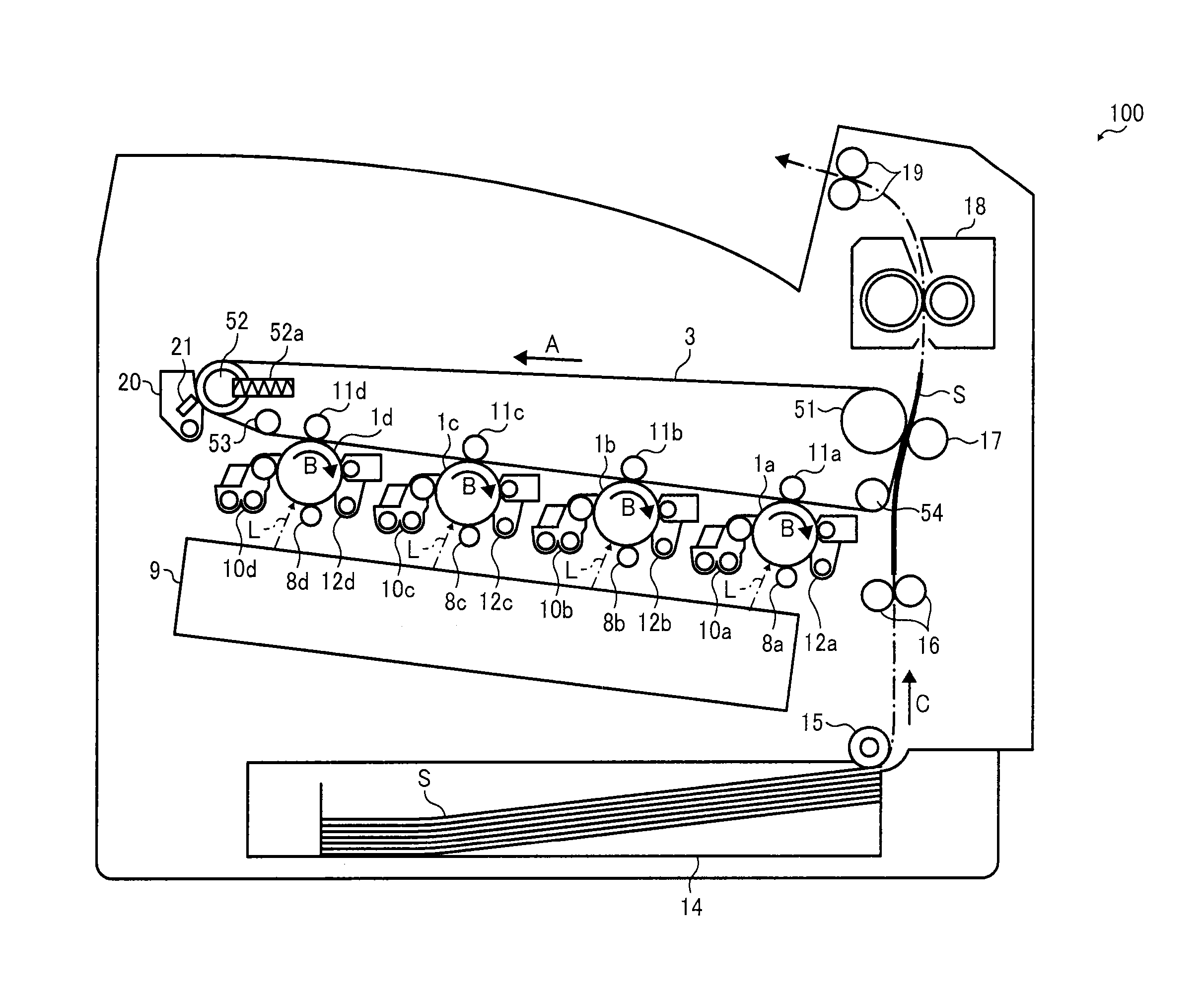
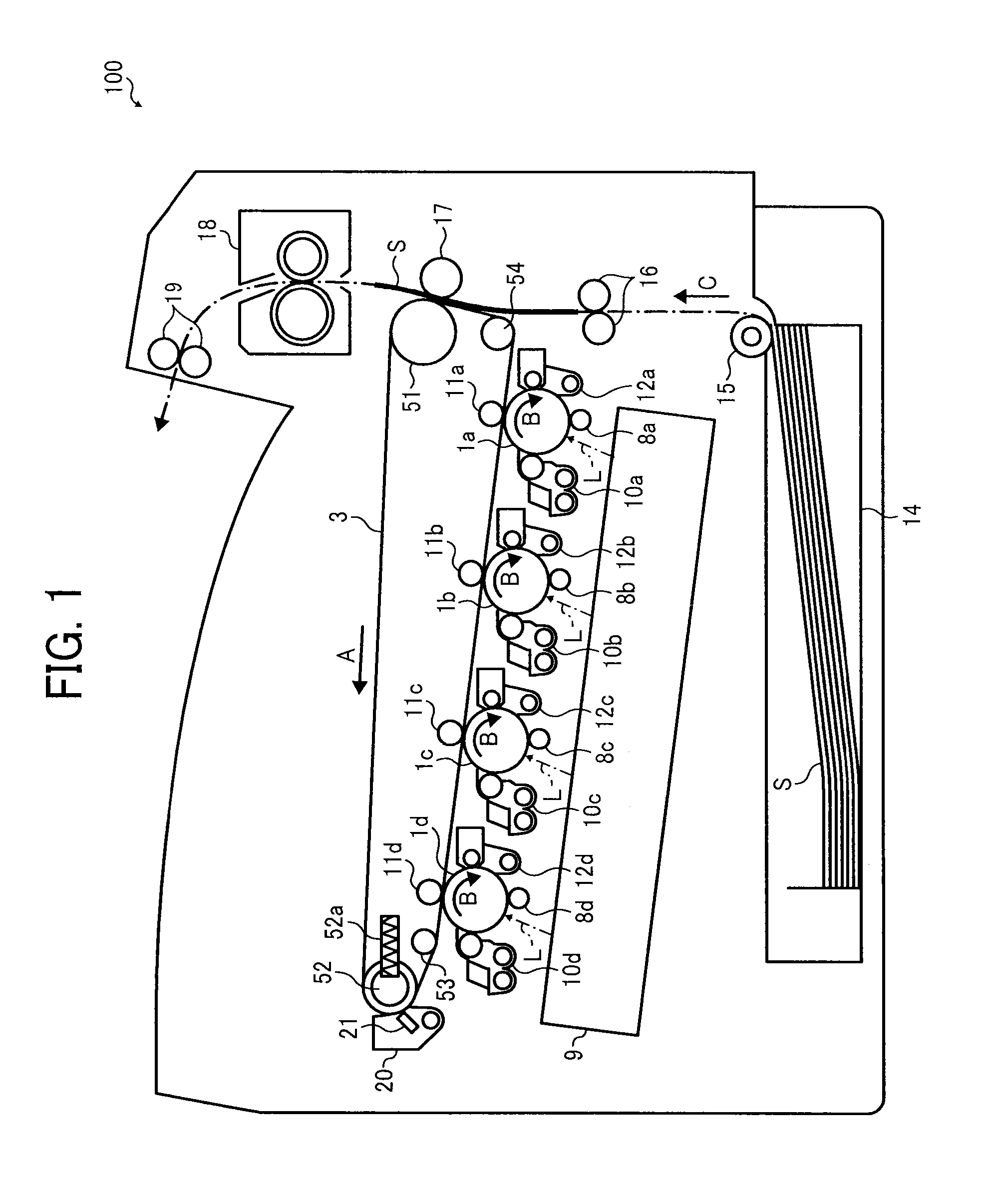
[0024]FIG. 1 schematically illustrates an image forming apparatus 100 according to one or more embodiments of this patent specification.

[0025]As shown in FIG. 1, the image forming apparatus 100 comprises a tandem color printer that employs four imaging stations, including first through fourth photoconductors 1a, 1b, 1c, and 1d arranged in series, for forming toner images with fo...


PUM


Abstract

A belt tracking system for controlling the lateral position of a movable belt entrained about a plurality of generally parallel rollers for moving in a trans-axial direction perpendicular to an axial direction in which the rollers extend parallel to each other includes a roller shaft, a stationary member, a slidable member, and a biasing mechanism. The roller shaft extends outward in the axial direction from an axial end of a specific one of the plurality of generally parallel rollers. The stationary member is fixed in position adjacent to the roller shaft to define a first interfacial surface therealong. The slidable member is co-movably coupled with the roller shaft to define a second interfacial surface therealong inclined relative to the axial direction. The biasing mechanism is connected to the roller shaft to press the slidable member against the stationary member.

Description

CROSS-REFERENCE TO RELATED APPLICATION[0001]The present patent application claims priority pursuant to 35 U.S.C. §119 from Japanese Patent Application No. 2012-149477, filed on Jul. 3, 2012, which is hereby incorporated by reference herein in its entirety.BACKGROUND OF THE INVENTION[0002]1. Technical Field[0003]The present invention relates to a belt tracking system, a multi-roller assembly and an image forming apparatus employing the same, and more particularly, to a belt tracking system for controlling the lateral position of a movable belt entrained about a plurality of rollers, and a multi-roller assembly and an image forming apparatus employing the belt tracking system.[0004]2. Background Art[0005]Image forming apparatuses employ various types of movable imaging belts, such as an intermediate transfer belt, a media conveyance belt, and a fixing belt, each of which is entrained about a plurality of generally parallel rollers for moving in a trans-axial direction perpendicular to...

Claims


Application Information

Patent Timeline
IPC IPC(8): B65G15/60
CPCB65G15/60G03G15/1615G03G2215/00156B65G39/16
Inventor HOZUMI, YOSHIKIASAOKA, AKIRASAWAI, YUUJISAEKI, KAZUCHIKA
Owner RICOH KK
Why Eureka
Eureka Blog
Learn More