Rope grab

a technology of ropes and ropes, applied in the field of ropes, to achieve the effect of a slight biasing for

Active Publication Date: 2014-01-23
D B IND
View PDF27 Cites 34 Cited by
  • Summary
  • Abstract
  • Description
  • Claims
  • Application Information

AI Technical Summary

Problems solved by technology

Systems that protect workers during fall events that can occur while climbing or descending on structures such as ladders and the like can be a challenge because of the varying vertical locations of the worker in relation to a support structure.

Method used


Image

  • Rope grab
  • Rope grab
  • Rope grab

Examples


Embodiment Construction

[0063]In the following detailed description, reference is made to the accompanying drawings, which form a part hereof, and in which is shown by way of illustration specific embodiments in which the inventions may be practiced. These embodiments are described in sufficient detail to enable those skilled in the art to practice the invention, and it is to be understood that other embodiments may be utilized and that changes may be made without departing from the spirit and scope of the present invention. The following detailed description is, therefore, not to be taken in a limiting sense, and the scope of the present invention is defined only by the claims and equivalents thereof.

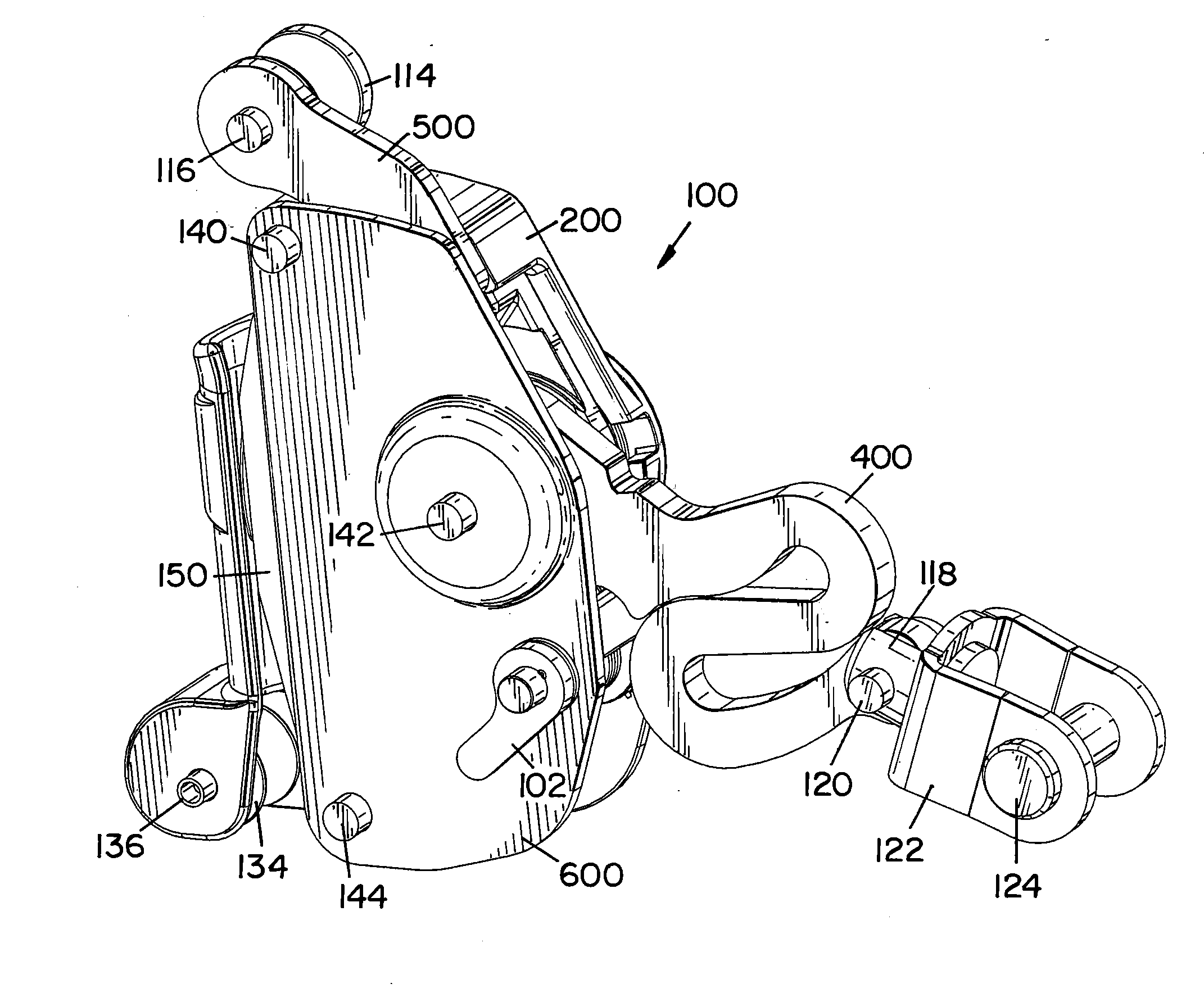
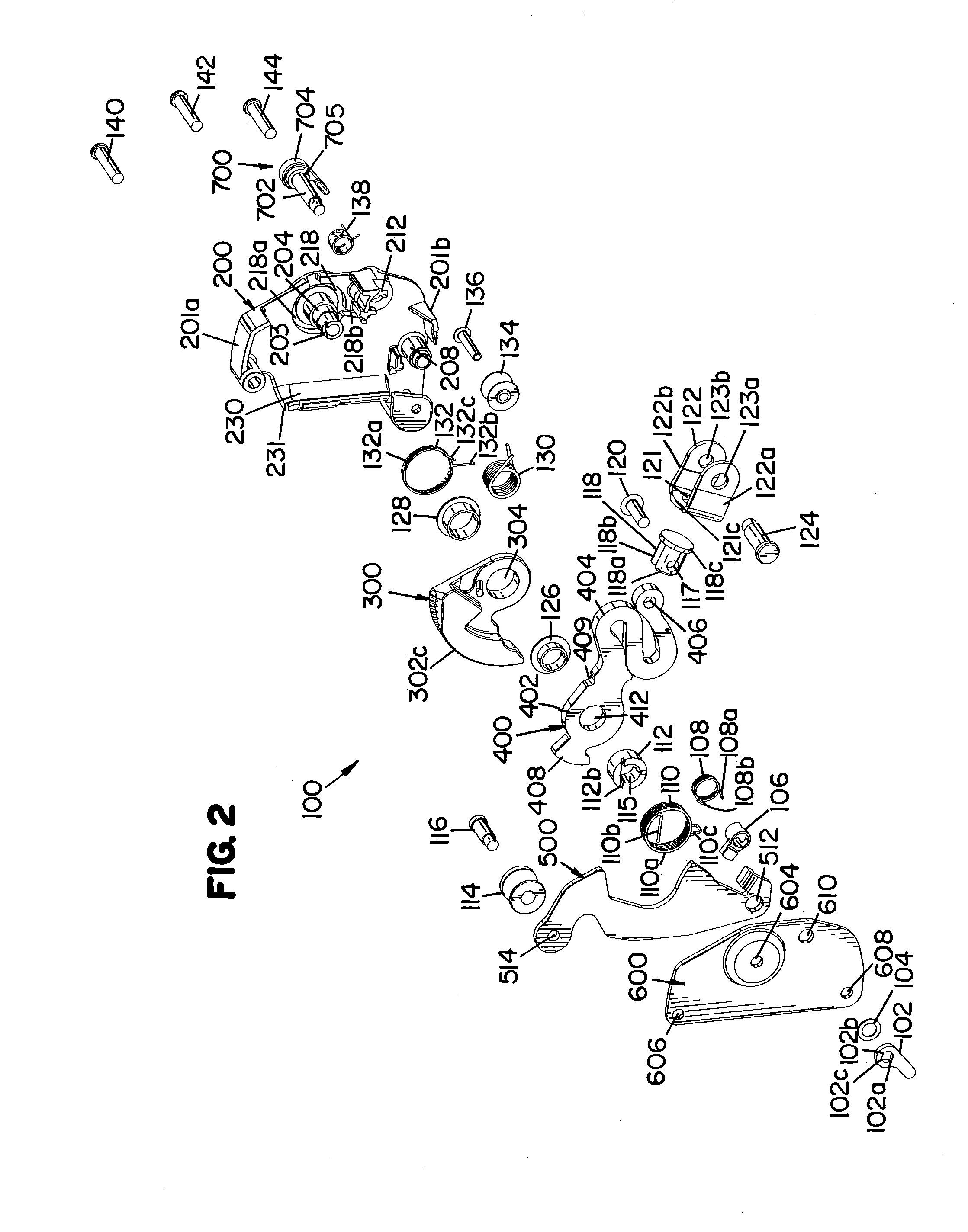
[0064]Embodiments of the present invention provide a rope grab (cable grab) used for fall protection that can be easily manipulated with one hand to attach and detach the rope grab from an elongated member such as a rope, cable or the like used as a support structure. Embodiments of the rope grabs 100, 1000 a...


PUM


Abstract

A rope grab for a vertical fall protection system is provided. The rope grab includes a housing with an elongated member passage. The elongated member passage is configured to receive an elongated member. A locking cam is pivotally coupled to the housing and selectively engages an elongated member received in the elongated member passage. A cam biasing member positioned to provide a relatively slight biasing force on the locking cam in a direction towards an elongated member received in the elongated member passage. A locking arm, pivotally coupled to the housing, has a first end that is configured to be coupled to a safety harness of a user and a second end that selectively engages the locking cam to lock the locking cam on an elongated member in the elongated member passage during a fall event.

Description

CROSS-REFERENCE TO RELATED APPLICATIONS[0001]This application is a Continuation-In-Part of U.S. Provisional application Ser. No. 13 / 551,845, same title herewith, filed on Jul. 18, 2012, and herein claims priority to said application and incorporates said application in its entirety herein by reference.BACKGROUND[0002]Regulations typically require workers who work at heights to don a safety harness that is coupled to a support structure so that if a fall event occurs, the fall is limited, therein reducing the chances of injuries to the worker. Systems that protect workers during fall events that can occur while climbing or descending on structures such as ladders and the like can be a challenge because of the varying vertical locations of the worker in relation to a support structure.[0003]For the reasons stated above and for other reasons stated below which will become apparent to those skilled in the art upon reading and understanding the present specification, there is a need in t...

Claims


Application Information

Patent Timeline
Patent Type & Authority Applications(United States)
IPC IPC(8): A62B35/00
CPCA62B35/0081A62B1/14A62B35/005A62B35/04
Inventor CASEBOLT, SCOTT C.BLOMBERG, JOHN P.MILLER, RICK G.
Owner D B IND
Why Eureka
Try Eureka