Drawer slide and electronically actuated locking mechanism

a technology of electronic action and locking mechanism, which is applied in the direction of construction fastening devices, furniture parts, safes, etc., can solve the problems of inability to provide convenient access to drawer contents, inability to control the contents of drawers, and inability to provide convenient access. , to achieve the effect of convenient access, more secure storage, for example as provided by a safe or a lock box, and not always desired

Active Publication Date: 2014-01-23
STANDARD PURISHIJIYAN
View PDF5 Cites 36 Cited by
  • Summary
  • Abstract
  • Description
  • Claims
  • Application Information

AI Technical Summary

Benefits of technology

[0010]These and other aspects of the invention are more fully comprehended upon review of this disclosure.

Problems solved by technology

Unfortunately, uncontrolled easy access to contents of a drawer is not always desired.
Secure storage of such items may be an important consideration, and drawer slides, with the ease of access they provide, may not be an appropriate.
More secure storage, for example as provided by a safe or a lock box, may also not always be appropriate.
Moreover, structures associated with safes and lock boxes may be somewhat bulky, and not easily incorporated in a cabinet type structure which otherwise may be desired.

Method used


Image

  • Drawer slide and electronically actuated locking mechanism
  • Drawer slide and electronically actuated locking mechanism
  • Drawer slide and electronically actuated locking mechanism

Examples


Embodiment Construction

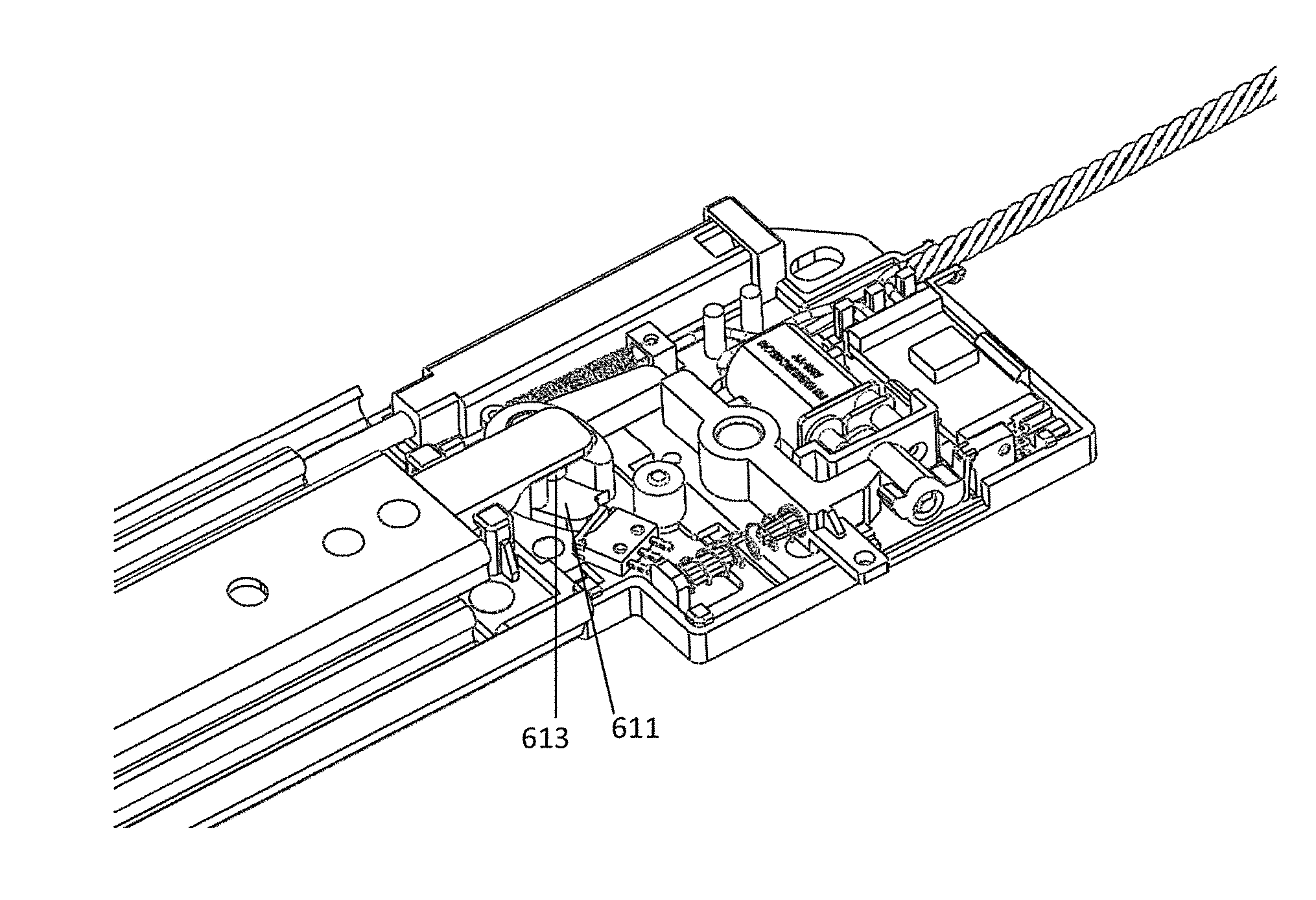
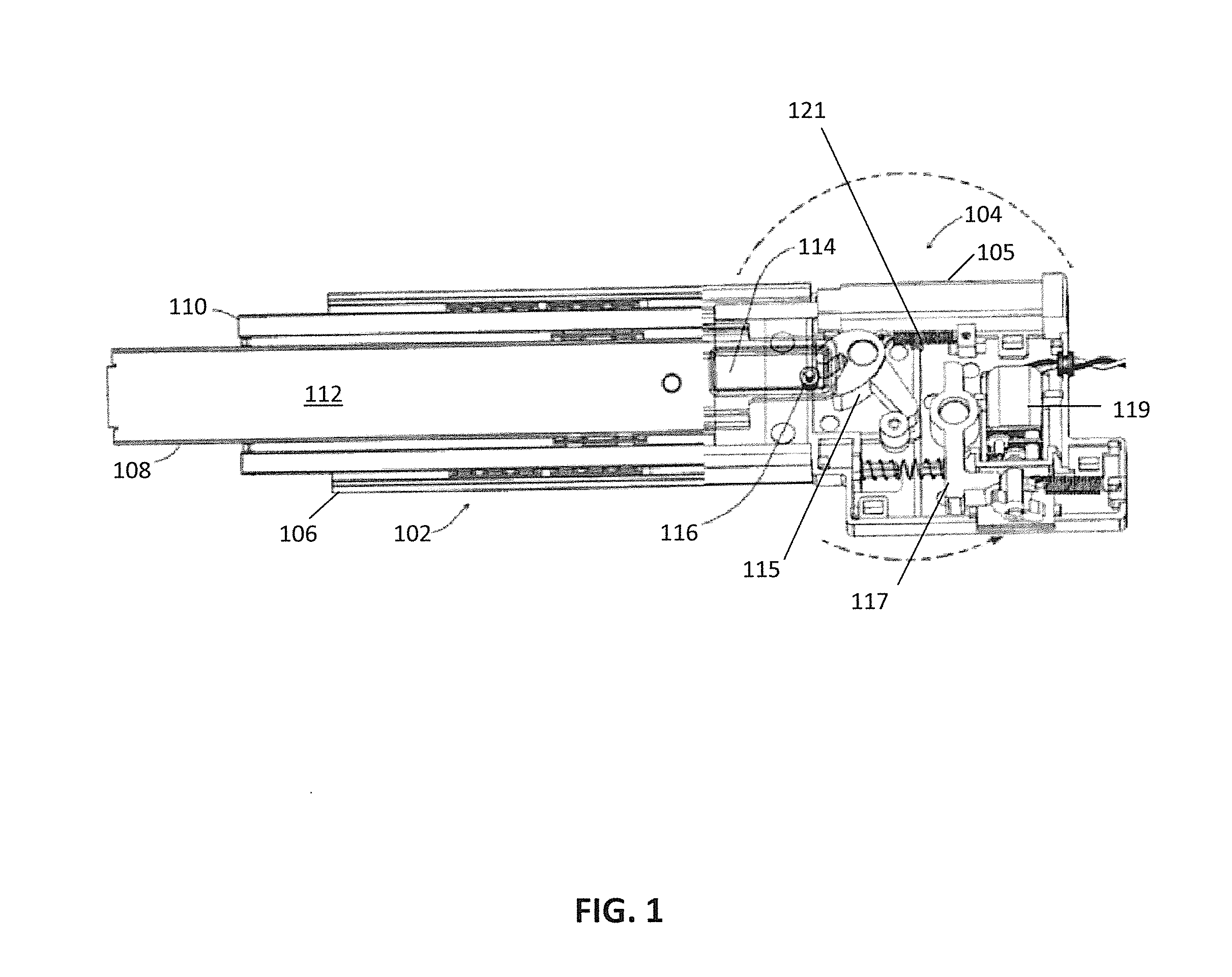
[0023]FIG. 1 illustrates a view of a drawer slide 102 with a lock mechanism 104 in accordance with an embodiment of the present invention. Generally, in the embodiment of FIG. 1, a latch arm is positioned on a portion of a drawer slide member that is intended to be mounted to and move with a drawer and the lock mechanism is coupled to a drawer slide member that is intended to be mounted to and maintained in position with respect to a cabinet. As illustrated the lock mechanism is coupled to a portion of a drawer slide member intended to be mounted to a cabinet, although in some embodiments the lock mechanism may be mounted to the cabinet. In most embodiments, the lock mechanism is dimensioned so as to fit within an operating envelope of the drawer slide, and in some embodiments the lock mechanism is mounted within the operating envelope of the drawer slide. The operating envelope of the drawer slide is generally a space having a width less than or equal to spacing between a cabinet w...


PUM


Abstract

An electrically actuated locking mechanism may include a microprocessor for control of the locking mechanism, and the locking mechanism may be used to lock a drawer slide in a closed position. The microprocessor may be in a housing of the locking mechanism, and the microprocessor may command a motor to operate in a first direction to drive lock components to a locked status and command the motor to operate in a second direction to drive the lock components to an unlocked state.

Description

CROSS REFERENCE TO RELATED APPLICATIONS[0001]This application claims the benefit of the filing date of U.S. Provisional Patent Application No. 61 / 673,159, filed Jul. 18, 2012, the disclosure of which is incorporated by reference herein.BACKGROUND OF THE INVENTION[0002]The present invention relates generally to drawer slides, and more particularly to drawer slides with locking mechanisms.[0003]Drawer slides are often used to extendably couple drawers within cabinets or racks within frames. Using a cabinet application as an example, drawer slides generally have one member mounted to a drawer and another member mounted to a cabinet. The two members are extendably coupled together, often by way of ball bearings, so that the extension of the drawer slide provides for extension of the drawer from the cabinet, allowing for easy access to the contents of the drawer.[0004]Unfortunately, uncontrolled easy access to contents of a drawer is not always desired. A drawer may contain items of a pe...

Claims


Application Information

Patent Timeline
Patent Type & Authority Applications(United States)
IPC IPC(8): E05B47/00E05B65/46A47B88/493
CPCE05B47/0001E05B65/46E05B47/0012E05B47/06E05C3/24E05B2047/0024E05B2047/0069E05B2047/0094Y10T70/7062A47B88/40E05B65/44E05G1/08
Inventor HASHEMI, DARUSH DAVIDZHOU, XIAOPINGCHI, QUINN
Owner STANDARD PURISHIJIYAN
Why Eureka
Try Eureka