Clock and data recovery for burst-mode serial signals

a serial signal and clock technology, applied in the field of clock and data recovery circuits for use with burst-mode serial signals, can solve the problems of objectionably long burst-mode communication systems, short initial locking time compared to the total time, undue reduction of communication bandwidth

Active Publication Date: 2013-04-09
MICROSEMI STORAGE SOLUTIONS
View PDF10 Cites 14 Cited by
  • Summary
  • Abstract
  • Description
  • Claims
  • Application Information

AI Technical Summary

Benefits of technology

[0006]In another aspect the invention provides a method for clock and data recovery, including sampling a serial input signal at distinct time points to produce sampled signals, where multiple time points occur in each bit time of the serial input signal; determining a phase for use in providing output data, the determining a phase comprising finding a data transition in the sampled signals; and providing output data by utilizing the phase to select among the sampled signals.
[0007]These and other aspects of the invention are more fully comprehended upon review of this disclosure.

Problems solved by technology

In addition, as each burst may be relatively short, an initial locking time that was very short compared to the total time of data communication in an always-on communication system may be objectionably long in a burst-mode communication system.
Furthermore, since the preambles of bursts are system overhead and do not convey useful data, use of lengthy preambles, for example, to allow for recovery of clock information, may unduly reduce communication bandwidth.

Method used


Image

  • Clock and data recovery for burst-mode serial signals
  • Clock and data recovery for burst-mode serial signals
  • Clock and data recovery for burst-mode serial signals

Examples


Embodiment Construction

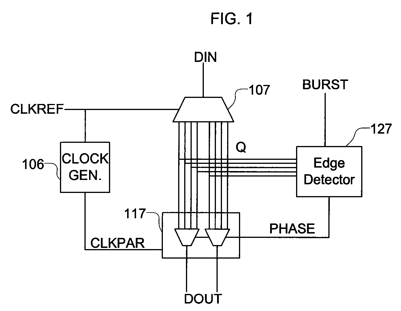
[0013]FIG. 1 is a block diagram of a clock and data recovery circuit (CDR) of a receiver in accordance with aspects of the invention. The CDR receives a serial input signal DIN that conveys a serial stream of data bits. The CDR receives data on the serial input signal DIN at a known nominal data rate. For example, the nominal data rate may be 1244.16 Mbps, but the actual data rate may vary, or have a tolerance of, 32 parts per million. The sequential stream of data received by the CDR includes bursts of data separated by gaps in the data. Each burst of data arrives with possibly a deviation from the nominal data rate and a possibly different phase. The bursts of data may begin with a preamble that the CDR may utilize to determine the timing of the burst. In some embodiments, the preamble includes a sequence of alternating ones and zeros.

[0014]A demultiplexer 107 of the CDR receives the serial input signal DIN. The demultiplexer 107 also receives a clock signal CLKREF. In one embodim...


PUM


Abstract

A clock and data recovery device recovers data from a sequential stream of data that includes bursts of data separated by gaps. Each burst of data arrives with its own phase and with its own deviation from a nominal frequency. The bursts of data begin with a preamble that is utilized to determine the timing of the burst. The clock and data recovery device determines the timing of a burst of data using signals from one or more demultiplexers or samplers. At the start of each burst of data, sampled input signals are analyzed by an edge detector to determine a sample phase for the burst. A selector utilizes the sample phase determined by the edge detector to choose which of the sampled input signals to use to produce output data signals from the clock and data recovery device.

Description

BACKGROUND OF THE INVENTION[0001]The present invention relates generally to clock and data recovery circuits and, more particularly, to clock and data recovery circuits for use with burst-mode signals.[0002]Some communication systems transmit data serially over a channel such as a fiber optic cable. A transmitter in a serial communication system transmits data in a data signal with clocking information signaled implicitly in the timing of transitions in the data signal. A receiver recovers both clock and data from the data signal. The receiver may use many bit times of received data to begin recovering the clock and data. In addition, data may be preceded by or include preambles to aid in recovery of, for example, clock information. This initial locking time is generally of little concern in always-on communication systems, considering that the initial locking time is very short compared to the total time of data communication.[0003]In some serial communication systems, data are gro...

Claims


Application Information

Patent Timeline
Patent Type & Authority Patents(United States)
IPC IPC(8): H04L7/00
CPCH04L7/0338H03K7/00H04L7/02
Inventor KYLES, IANPAHOMSKY, EUGENE
Owner MICROSEMI STORAGE SOLUTIONS
Why Eureka
Try Eureka