Antenna

a technology of antennas and antenna components, applied in the field of antennas, can solve the problems of easy bending or breaking of external antennas upon impact, and achieve the effects of reducing the shortening rate of wavelength, reducing the use rate of antenna materials, and improving antenna efficiency

Inactive Publication Date: 2014-01-23
PEGATRON
View PDF3 Cites 0 Cited by
  • Summary
  • Abstract
  • Description
  • Claims
  • Application Information

AI Technical Summary

Benefits of technology

[0010]The coaxial cable is directly applied as a conductor antenna member in the present invention so as to reduce the shorten rate of the wavelength caused by the dielectric constant of the material, so that the efficiency of the antenna is improved and becomes comparable with an external dipole antenna. Further, the usage rate of the materials for manufacturing the antenna is reduced so as to reduce the cost of the antenna. Additionally, the fixing member is provided to fix the positions of the radiating portion and the grounding portion via an incompletely enclosing manner so as to keep the radiating direction and protect the radiating portion and the grounding portion.

Problems solved by technology

Aside from the volume and the aesthetic issues, the external antennas suffer bending or breaking easily upon impact.
Additionally, on assembly, the special limitation must be considered because of the volume of the conductor antenna member and the shape-unchangeable character of the conductor antenna member.

Method used


Image

  • Antenna
  • Antenna
  • Antenna

Examples


Embodiment Construction

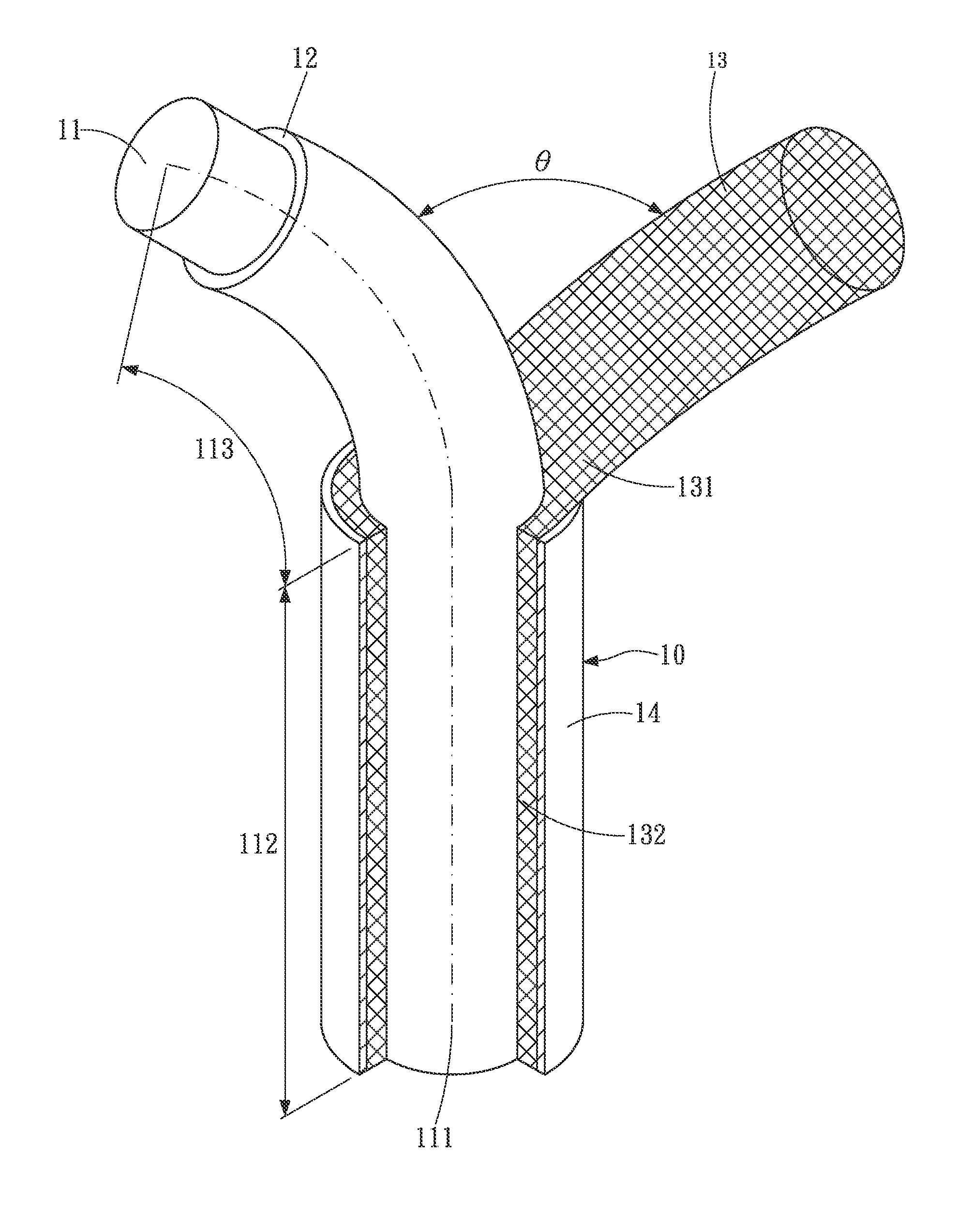
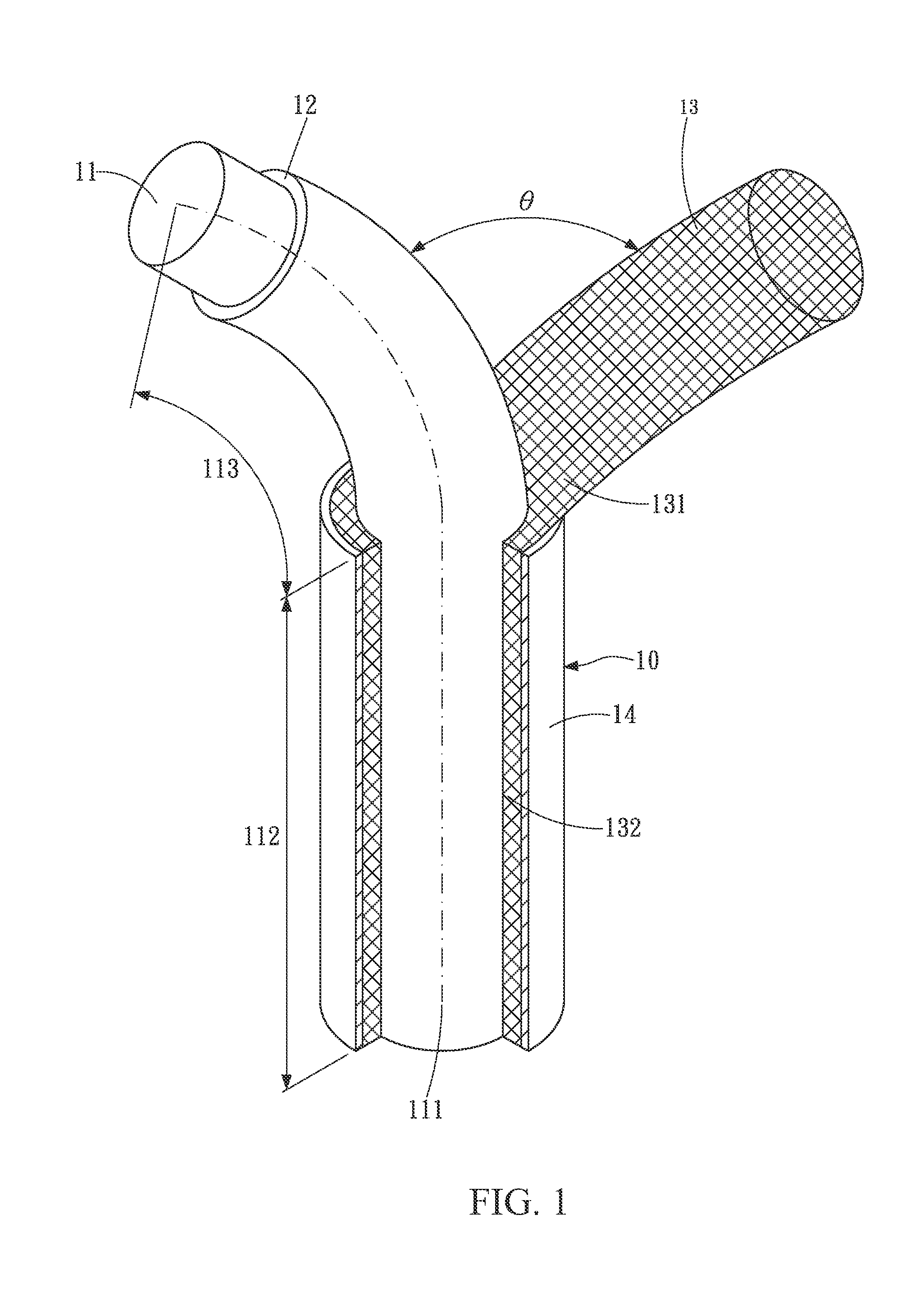
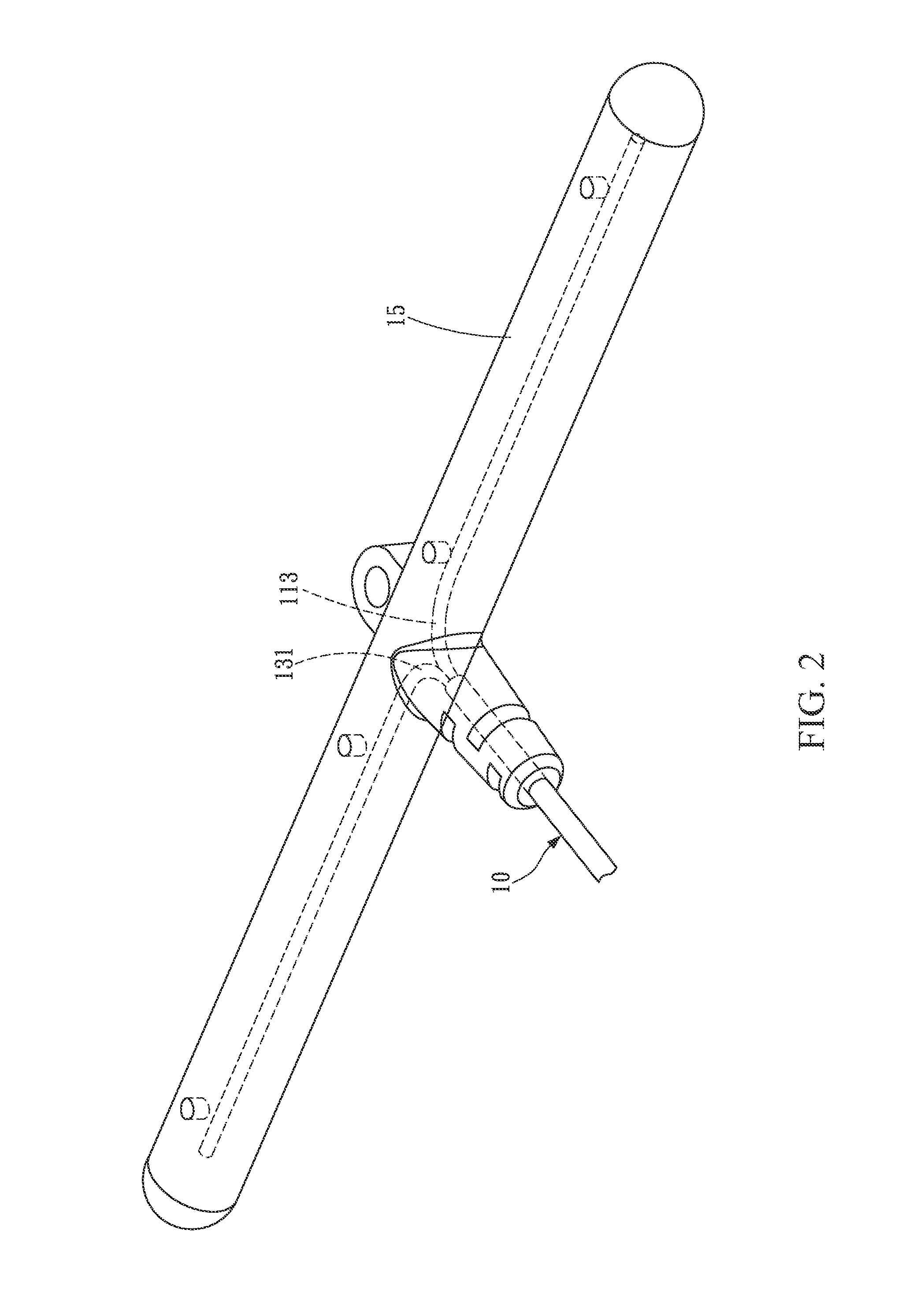
[0017]FIG. 1 is a cross-sectional view of an antenna of a first embodiment of the present invention. Please refer to FIG. 1, the antenna is substantially composed of a coaxial cable 10.

[0018]The coaxial cable 10 includes a core wire 11, an inner insulating layer 12, a metal layer 13 and an outer insulating layer 14. The inner insulating layer 12, the metal layer 13 and the outer insulating layer 14 are annularly coated on the core wire 11 in order.

[0019]The core wire 11 includes a signal feeding portion 111, a connecting portion 112 and a radiating portion 113. The connecting portion 112 is electrically connected to the signal feeding portion 111 and the radiating portion 113. Here, the signal feeding portion 111 and the radiating portion 113 are located at two opposite ends of the connecting portion 112 respectively. That is to say, the core wire 11 can be divided into the signal feeding portion 111, the connecting portion 112 and the radiating portion 113. In some embodiments, the...


PUM


Abstract

An antenna is provided, and includes a coaxial cable. The coaxial cable includes a core wire, an inner insulating layer, a metal layer and an outer insulating layer. The core wire includes a signal feeding portion, a connecting portion and a radiating portion. The connecting portion is electrically connected to the signal feeding portion and the radiating portion. The inner insulating layer encloses the connecting portion. The metal layer partially encloses the inner insulating layer. Parts of the metal layer are separated from the inner insulating layer and include a grounding portion. The outer insulating layer partially encloses the metal layer, and the grounding portion is exposed.

Description

CROSS-REFERENCES TO RELATED APPLICATIONS[0001]This non-provisional application claims priority under 35 U.S.C. §119(a) on Patent Application No. 101213866 filed in Taiwan, R.O.C. on Jul. 18, 2012, the entire contents of which are hereby incorporated by reference.BACKGROUND[0002]1. Technical Field[0003]The disclosure relates to an antenna.[0004]2. Related Art[0005]Antennas are mainly classified as external antennas and internal antennas, in which the external antennas are assembled out of the device and the internal antennas are assembled in the device. Aside from the volume and the aesthetic issues, the external antennas suffer bending or breaking easily upon impact. Consequently, internal antennas have become increasingly popular.[0006]As known in prior arts, mostly a coaxial cable is used as the feeding cable in the conventional antenna assembled on the electric device for receiving and sending wireless signals, and a conductor antenna member, such as a PCB conductor antenna membe...

Claims


Application Information

Patent Timeline
Patent Type & Authority Applications(United States)
IPC IPC(8): H01Q1/36H01Q1/48
CPCH01Q1/36H01Q1/48H01Q1/243H01Q9/20
Inventor TSAO, WEI-CHUN
Owner PEGATRON
Why Eureka
Try Eureka