
Appliance for drying laundry

a technology for drying clothes and laundry, applied in the direction of washing machines, lighting and heating equipment, applications, etc., can solve the problems of cumbersome tasks and inability to provide electrical resistance, and achieve the effect of reducing the encumbrance of components necessary

Active Publication Date: 2014-01-30
ELECTROLUX HOME PROD CORP NV
View PDF20 Cites 45 Cited by
  • Summary
  • Abstract
  • Description
  • Claims
  • Application Information

AI Technical Summary

Benefits of technology

The patent text describes a solution to reduce the size and weight of components needed for a laundry drying appliance, by integrating a top into the cabinet of the appliance. This top contains a moisture condensing module for dehydrating drying air, a drying air inlet, a drying air outlet, and fluid passageways for the passage of drying air. The top can be easily mounted onto the cabinet and is designed to match the shape of the cabinet. The technical effect of this invention is to reduce the size and weight of the drying appliance, making it more portable and easier to install.

Problems solved by technology

Other known dryers and washers / dryers exploit a heat pump to dehydrate the drying air flow; in these dryers, the function of the heating arrangement may be performed by the heat pump itself, and the electrical resistance may thus not be provided for.
This may be a cumbersome task, because of space constraints.

Method used


Image

  • Appliance for drying laundry
  • Appliance for drying laundry
  • Appliance for drying laundry

Examples


Embodiment Construction

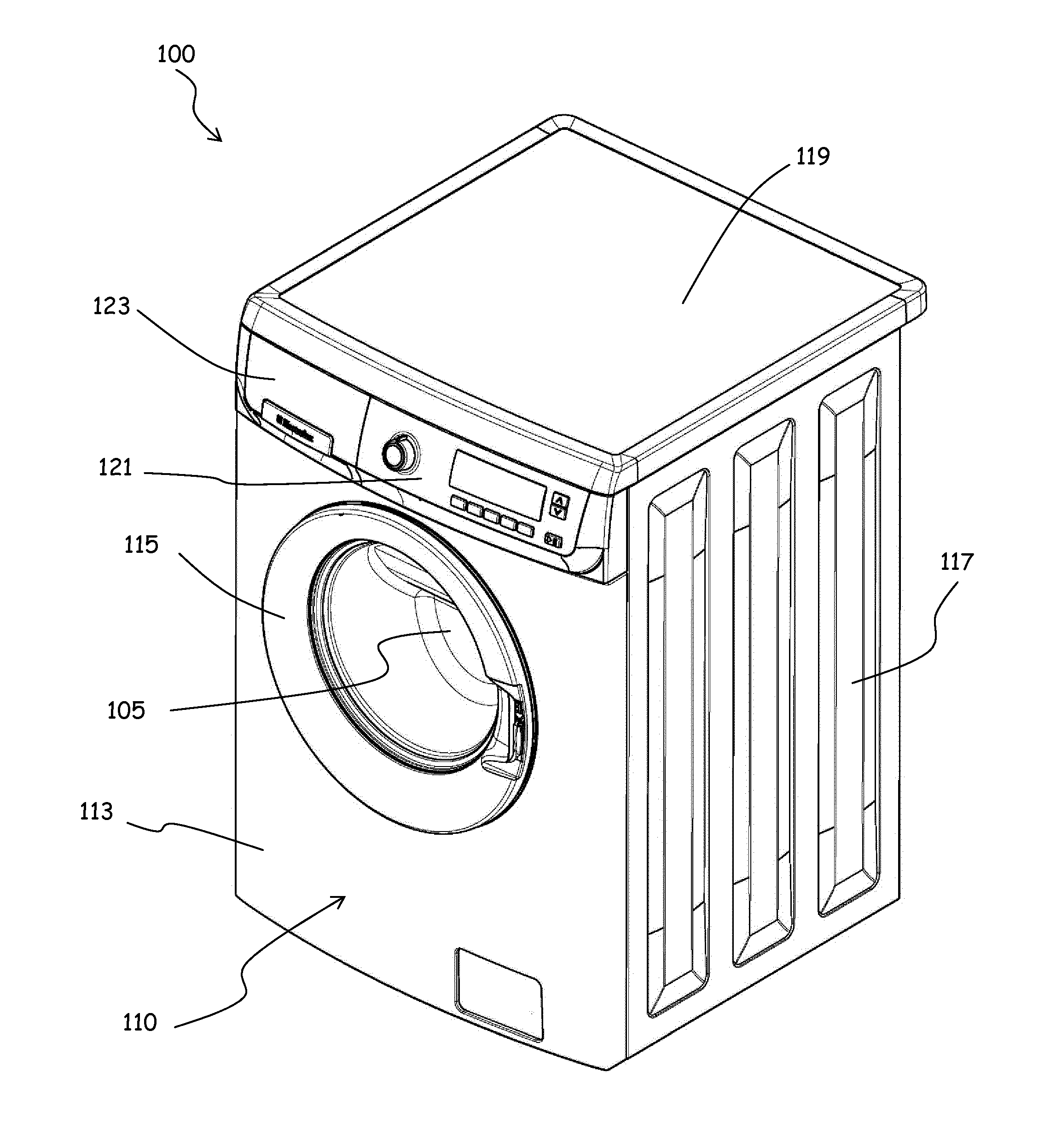
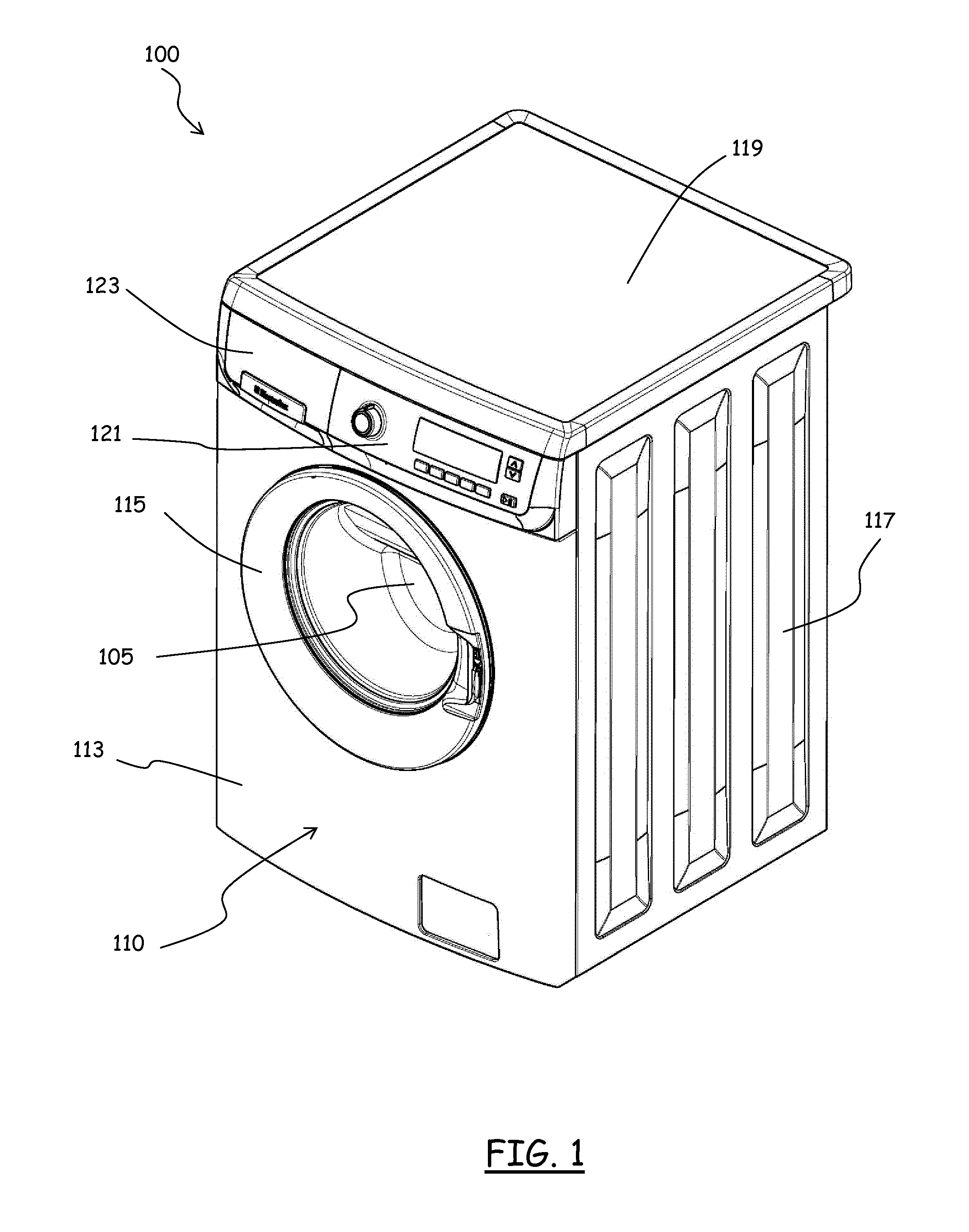
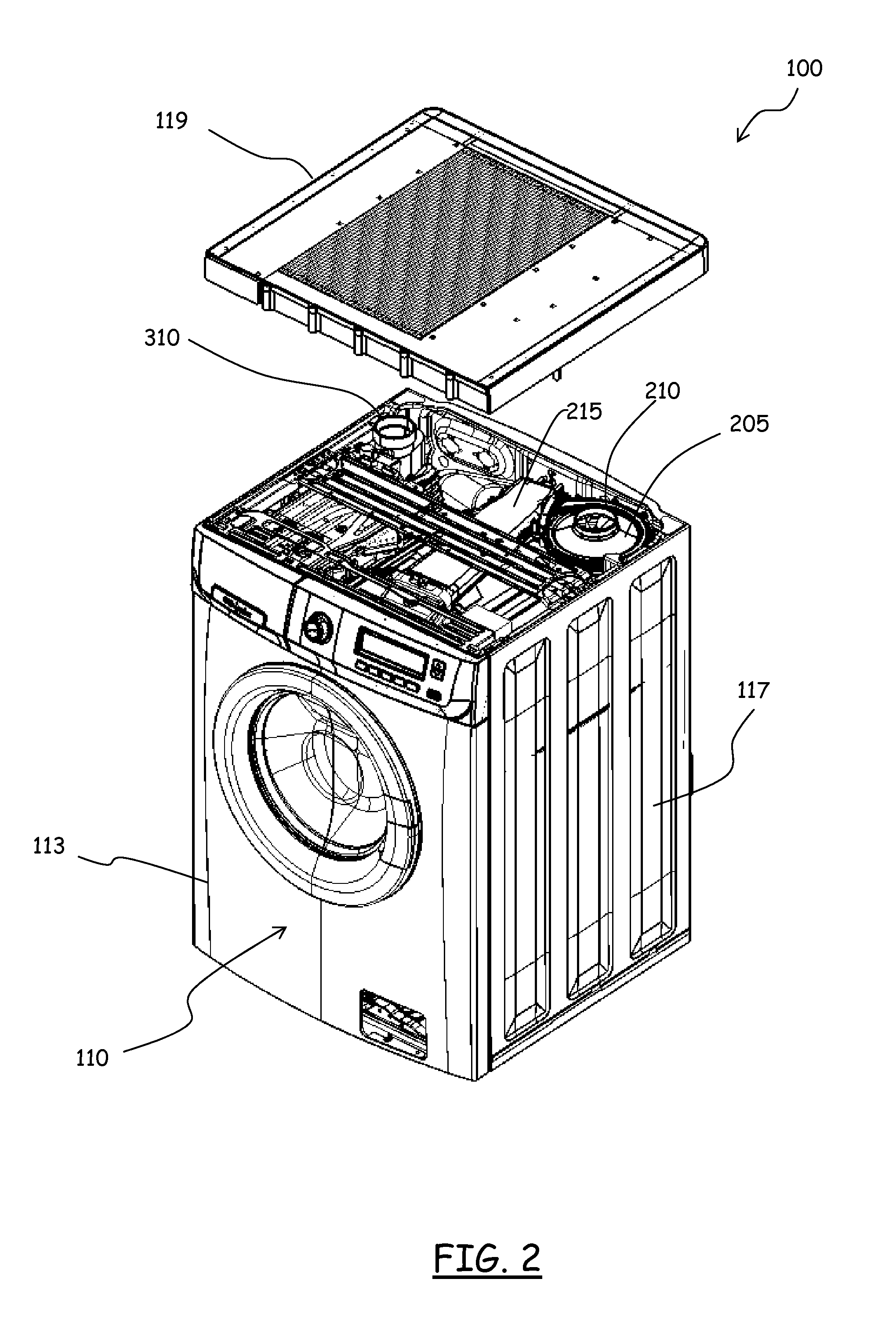
[0075]With reference to the drawings, a laundry drying appliance, particularly a washer / dryer according to an embodiment of the present invention is depicted in FIG. 1 in perspective. The washer / dryer, globally denoted as 100, comprises a drum 105 for the loading of the articles to be washed and / or dried, such as clothes, garments, linen, and similar articles. The drum 105 is a generically cylindrical body, for example made of stainless steel, and is rotatable within a tub housed in the machine casing or cabinet 110.

[0076]The cabinet 110 is generically a parallelepiped in shape, and has a front wall 113, two side walls 117, a rear wall, a basement and a worktop (top) 119. The front wall 113 is provided with an opening for accessing the drum 105 and with an associated door 115 for closing the opening. In the upper part of the front wall 113, a machine control panel 121 is located, and, aside the control panel 121, a drawer 123, part of a washing treatment products dispensing arrangem...


PUM


Abstract

A top adapted to match and close from above a cabinet of a laundry drying appliance, is provided. The top is formed as a ready-to-mount part ready to be mounted to the cabinet and forming a moisture condensing module for dehydrating drying air used to dry laundry within a drying drum of the laundry drying appliance. The top has a drying air inlet for receiving moisture-laden drying air, a drying air outlet for delivering demoisturized drying air, fluid passageways defined thereinside from the drying air inlet to the drying air outlet for the passage of the drying air to be dehydrated and a moisture condenser arranged inside the fluid passageways. The top includes, integrally formed therein, at least one structural part of the appliance, the at least one structural part of the appliance having at least one a part of: a housing of a fan for propelling the drying air; a drying air delivery duct connectable to a drying air inlet of the drying drum for delivering the drying air into the drying drum; a seat for a container of detergents / softener for washing laundry; a condense water collector for collecting condense water released by the moisture-laden drying air; at least part of a condense water draining system; a support for at least one water inlet valve for selectively allowing the intake of water from a water main; and at least part of a water circuit for delivering water to wash the moisture condensing means.

Description

BACKGROUND OF THE INVENTION[0001]1. Field of the Invention[0002]The present invention generally relates to the field of household appliances for laundry and garments treatment. In particular, the present invention relates to appliances for drying laundry, such as laundry dryers and combined washers / dryers.[0003]2. Discussion of the Related Art[0004]Appliances for drying laundry, are adapted to dry clothes, garments, laundry in general, by circulating hot, dry air within a tumbler or drum. The drum is rotatably accommodated within a machine cabinet, and is designed to contain the articles to be dried. The rotation of the drum causes agitation of the articles to be dried, while they are hit by the drying air flow.[0005]Combined laundry washer / dryer appliances combine the features of a washing machine with those of a dryer; in these appliances, the drum is rotatably accommodated within a washing tub.[0006]In a known type of laundry dryers and washers / dryers, also referred to as “conden...

Claims


Application Information

Patent Timeline
Patent Type & Authority Applications(United States)
IPC IPC(8): F26B25/16
CPCF26B25/16D06F39/12D06F58/02D06F58/16D06F58/18D06F58/24
Inventor BISON, ALBERTOCOLIN, IGORDEL POS, MAURIZIOOLIVARO, PAOLO
Owner ELECTROLUX HOME PROD CORP NV
Learn More