Method of manufacturing of cutting knives using direct metal deposition

a manufacturing method and cutting knife technology, applied in the field of cutting knives, can solve the problems of limited life of conventional heat-treated edges presently in use, and achieve the effects of reducing costs, prolonging service life, and improving micro-structure and mechanical properties

Active Publication Date: 2014-01-30
DM3D TECH
View PDF7 Cites 4 Cited by
  • Summary
  • Abstract
  • Description
  • Claims
  • Application Information

AI Technical Summary

Benefits of technology

[0004]This invention broadly uses direct metal deposition (DMD) to fabricate knife edges with extended service life, while reducing the costs associated with sharpening and other post-processing requirements. The rapid solidification associated with DMD offers fine microstructure with improved micro-structure and mechanical properties. Knives produced in accordance with the invention exhibit superior edges, in some cases exceeding three times the life of comparable products available in the market.

Problems solved by technology

Conventional heat-treated edges presently in use have a limited life.
Brazed carbide edges offer improved life, but failure at the brazed joint, and special requirements for sharpening carbide edges, makes them very expensive.

Method used


Image

  • Method of manufacturing of cutting knives using direct metal deposition
  • Method of manufacturing of cutting knives using direct metal deposition
  • Method of manufacturing of cutting knives using direct metal deposition

Examples


Embodiment Construction

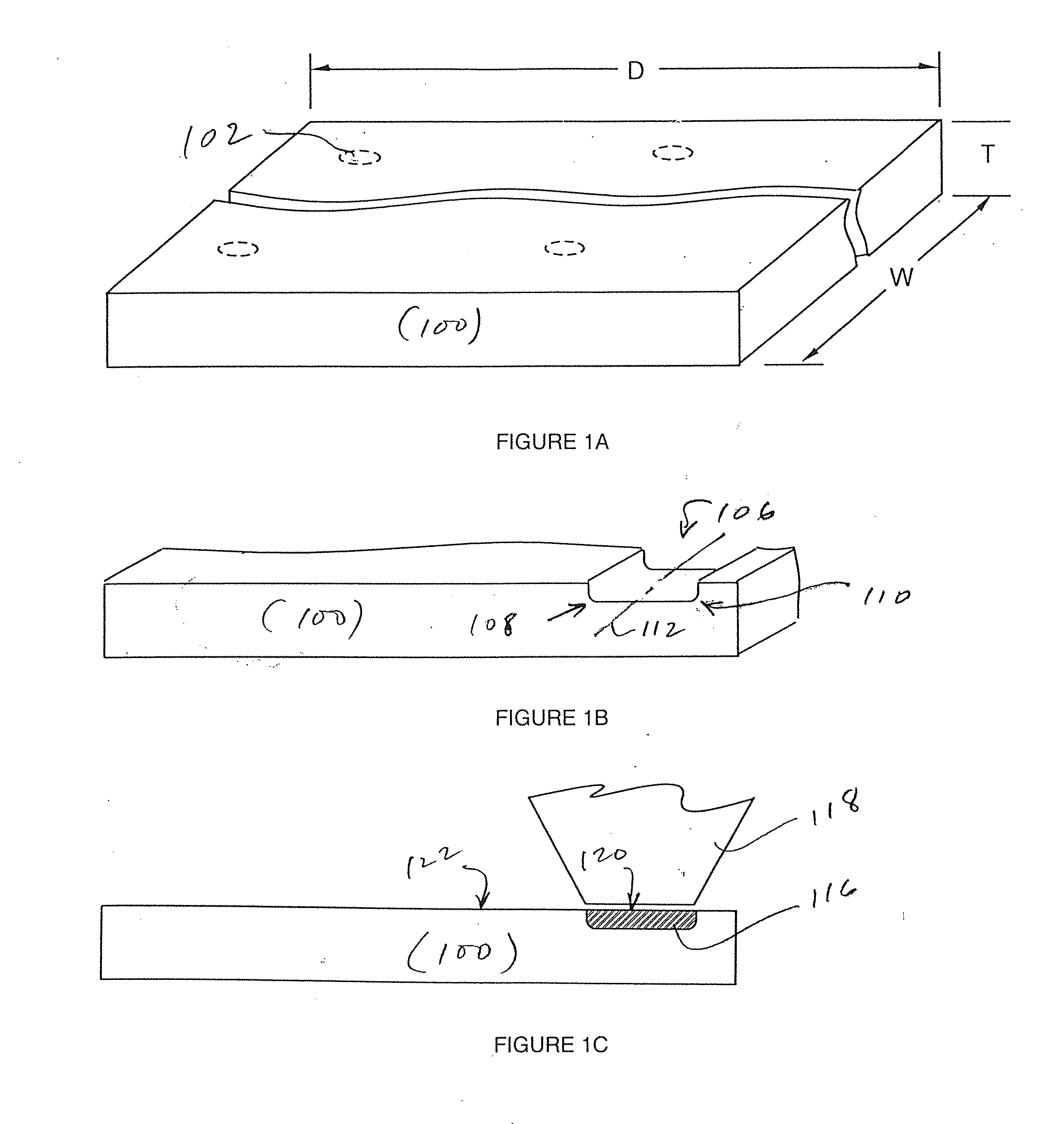
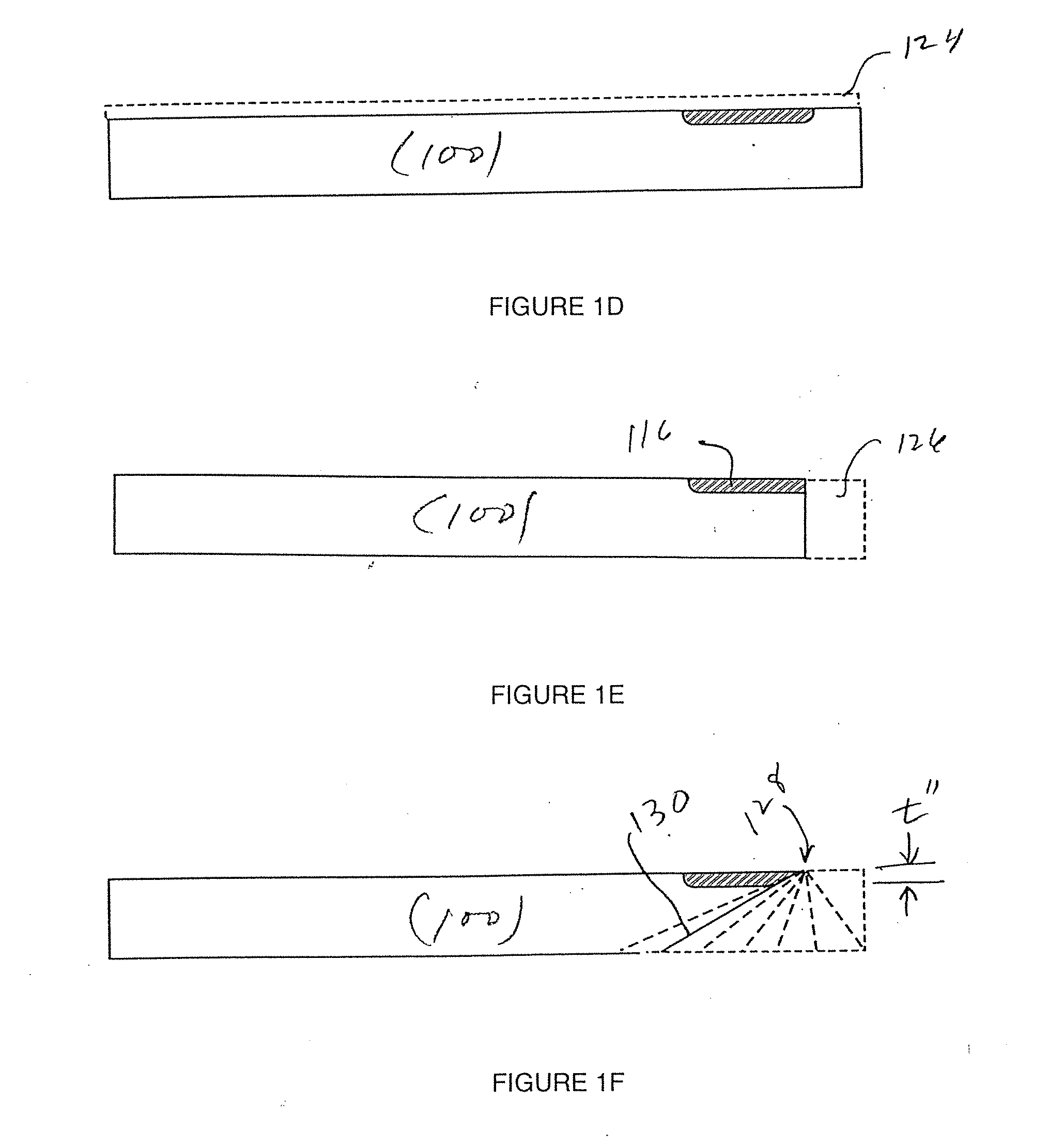
[0028]As an introduction, commonly assigned U.S. Pat. No. 6,122,564 describes a laser-aided, computer-controlled direct metal deposition (DMD) system wherein successive layers of material are applied to a substrate so as to fabricate an object or provide a cladding layer. The deposition tool path may be generated by a computer-aided manufacturing system, and feedback monitoring may be used to control the dimensions and overall geometry of the fabricated section in accordance with a computer-aided design description.

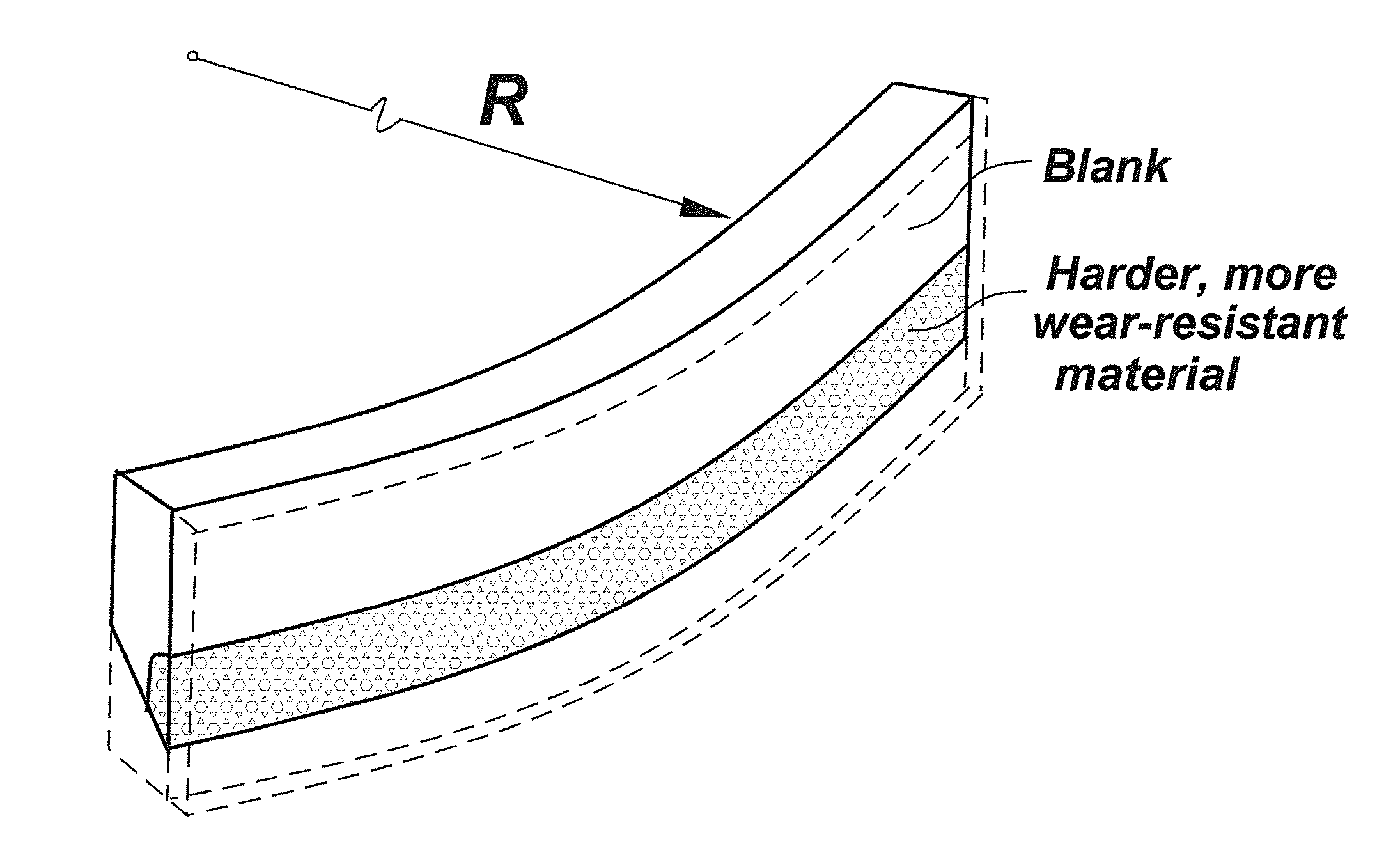
[0029]DMD systems are capable of depositing sections on metallic substrates of a differing material than used in the deposition, on the condition that suitable choices of material are made and suitable surface treatment is performed to achieve a good metallurgical bond between the deposited material and the underlying substrate.

[0030]This invention extends and improves upon the teachings set forth in the '564 Patent, the entire content of which is incorporated herein by r...


PUM

PropertyMeasurementUnit
cutting anglesaaaaaaaaaa
Raaaaaaaaaaa
thicknessaaaaaaaaaa

Abstract

Direct metal deposition (DMD) is used to fabricate knife edges with extended service life. A metal alloy powder is deposited along a blank and melted with a laser beam so that the powder solidifies into a strip of material having a hardness and / or wear resistance greater than that of the starting material. The piece is then finished to produce a sharp edge in the solidified material. The powder may be melted while it is being deposited, or it may be melted after being deposited. A slot or groove may be formed in the blank with the metal alloy powder being deposited into the slot or groove. A hardened steel alloy powder is deposited onto a mild steel blank. For example, a tool steel or vanadium steel powder may be deposited onto a 1018 steel blank. An invention line-beam nozzle may be used for deposition and / or powder melting.

Description

REFERENCE TO RELATED APPLICATION[0001]This application is a divisional of U.S. patent application Ser. No. 12 / 732,794, filed Mar. 26, 2010, which claims priority from U.S. Provisional Patent Application Ser. No. 61 / 163,591, filed Mar. 26, 2009, the entire content of both of which is incorporated herein by reference.FIELD OF THE INVENTION[0002]This invention related generally to cutting knives with hardened edges and, in particular, to knives, blades, shears, punches and other cutting or hole-forming implements wherein the hard edge material is fashioned with a direct-metal deposition (DMD) process as opposed to gluing, brazing or other bonding dissimilar materials.BACKGROUND OF THE INVENTION[0003]Cutting knives with durable sharp edges are needed in a wide variety of industries for cutting papers, coated papers, plastics, fibers, rubbers, card boards, films, foils, and biological tissues (i.e., in surgical applications). Conventional heat-treated edges presently in use have a limite...

Claims


Application Information

Patent Timeline
Patent Type & Authority Applications(United States)
IPC IPC(8): B26D1/00
CPCB26D1/0006B26B9/00C23C24/106Y10T83/929
Inventor DUTTA, BHASKARNATU, HARSHADSWENSON, W.MAZUMDER, JYOTI
Owner DM3D TECH
Why Eureka
Try Eureka