Inkjet recording machine

Active Publication Date: 2014-01-30
RISO KAGAKU CORP
View PDF1 Cites 4 Cited by
  • Summary
  • Abstract
  • Description
  • Claims
  • Application Information

AI Technical Summary

Benefits of technology

[0025]According to the above configuration, the power of sucking the recording medium to the conveyance route by use of a negative pressure is lower in printing a print image with a resolution above a predetermined value, than in printing a print image with a resolution at or below the predetermined value.
[0026]Thus, the power of sucking the recording medium to the conveyance route by use of a negative pressure is reduced only in printing a print image

Problems solved by technology

Thus, accompanying a preceding main drop, unnecessary minute drops (satellite drops) might be produced.
The satellite drops (also called mi

Method used


Image

  • Inkjet recording machine
  • Inkjet recording machine
  • Inkjet recording machine

Examples


Example

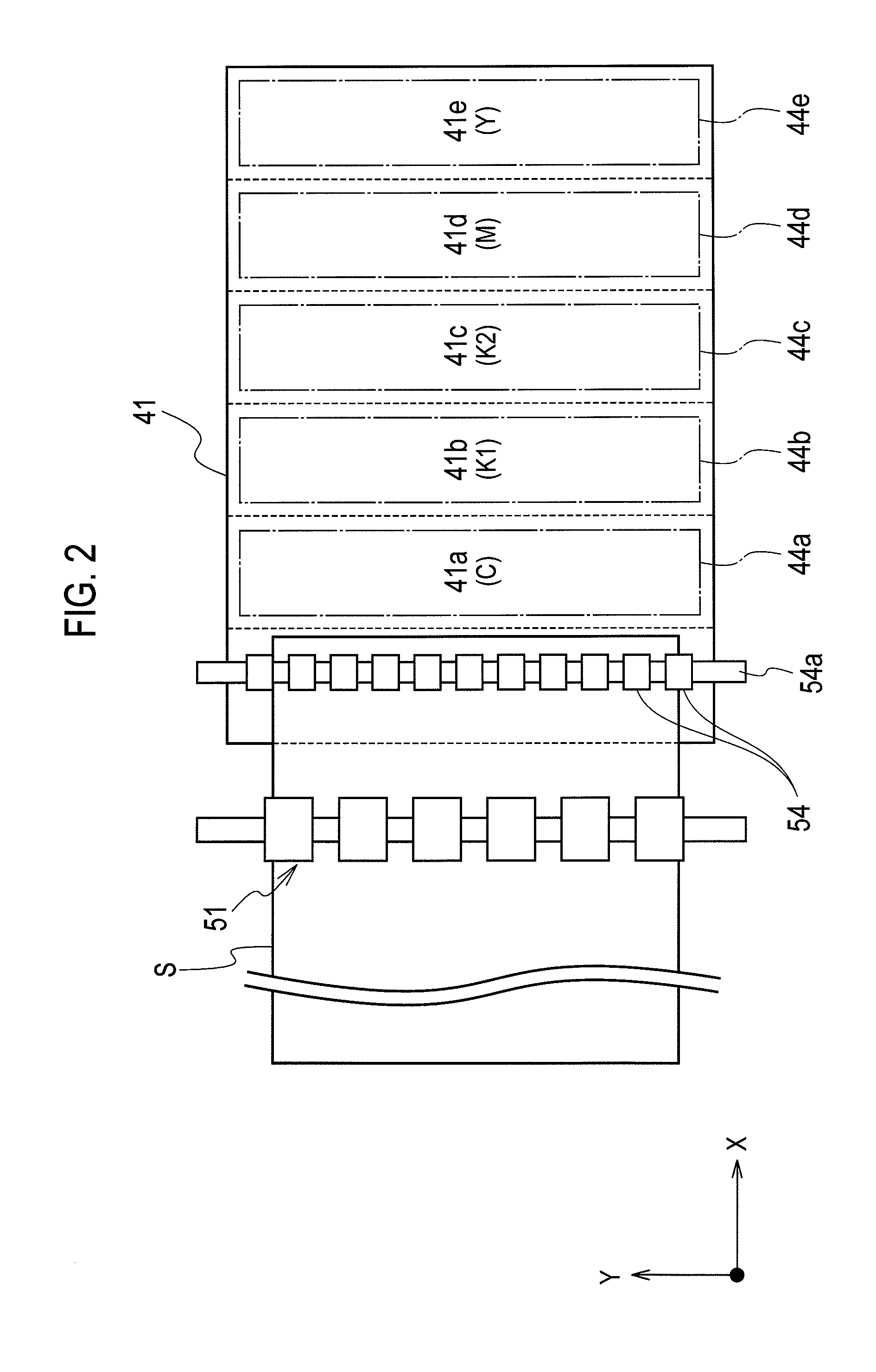
[0094]FIG. 7 is an enlarged plan view showing such an inkjet printer of a second embodiment. As shown in FIG. 7, in the above case, the suction fan unit 44 placed at the back of the belt platen 41 has four arrays of suction fans 44a to 44d arranged in the conveyance direction X extending in the left-right direction in FIG. 7. The suction fans 44a to 44d correspond to the inkjet heads 31 for C, K, M, and Y, respectively.

[0095]Specifically, the suction fan 44a generates a negative pressure for sucking the recording sheet S at a portion (first area) 41a of the belt platen 41 facing the inkjet head 31 for C (cyan). The suction fan 44b generates a negative pressure for sucking the recording sheet S at a portion (second area) 41b of the belt platen 41 facing the inkjet head 31 for B (black).

[0096]Moreover, the suction fan 44c generates a negative pressure for sucking the recording sheet S at a portion (third area) 41c of the belt platen 41 facing the inkjet head 31 for M (magenta). The su...


PUM


Abstract

A control unit is configured to form a print image on a recording medium by ejecting ink drops from nozzles of an ink head to the recording medium being conveyed on a conveyance route and sucked to the conveyance route by a negative pressure generated by a suction unit. The control unit is configured to control a level of suction power of sucking the recording medium to the conveyance route by the negative pressure in accordance with a level of a resolution of the print image in at least one of a main scanning direction or a sub scanning direction.

Description

CROSS REFERENCE TO RELATED APPLICATION[0001]This application is based upon and claims the benefit of priority from the prior Japanese Patent Application No. 2012-165485, filed on Jul. 26, 2012, the entire contents of which are incorporated herein by reference.BACKGROUND[0002]1. Technical Field[0003]The present invention relates to an inkjet recording machine configured to eject drops of ink in an ink chamber from a nozzle.[0004]2. Related Art[0005]In an inkjet recording machine, ink in an ink chamber provided at an inkjet head is ejected as a drop from a nozzle. The ink drop ejected from the nozzle flies with a tail, and there are a time lag and a speed difference between a head portion and a tail portion of this drop in flight. Thus, accompanying a preceding main drop, unnecessary minute drops (satellite drops) might be produced. The satellite drops (also called mist) degrade the printing quality by attaching onto a recording medium, and contaminate the device by attaching to the i...

Claims


Application Information

Patent Timeline
IPC IPC(8): B41J13/00
CPCB41J13/0009B41J11/0085B41J11/007B41J13/226
Inventor NISHIMURA, ASSAYO
Owner RISO KAGAKU CORP
Why Eureka
Try Eureka