
Thermally improved placement of power-dissipating components onto a circuit board

Inactive Publication Date: 2005-12-08
AVAGO TECH INT SALES PTE LTD
View PDF4 Cites 5 Cited by
  • Summary
  • Abstract
  • Description
  • Claims
  • Application Information

AI Technical Summary

Benefits of technology

[0020] Alternatively, in another preferred embodiment of the electronic system, the power dissipated via the top of said component is lower than the power dissipated via the bottom of said component. This can be achieved by, for example, selecting materials at the bottom of a package (metals etc.) that conduct heat better than materials at the top of the package (plastics etc.).

Problems solved by technology

For example, some packages are equipped with a built-in heatpad on the bottom side of the package, which results in a higher power dissipation through their bottom than through their top portion, i.e. PB>PT.
Other packages are equipped with a built-in heatpad or heatspreader on the top side of the package, which may result in a higher power dissipation through their top side than through their bottom side, i.e. PB<PT.
Still, overheating of the printed circuit board (PCB) and / or the integrated circuits might occur, leading e.g. to mechanical tensions (and even, the breaking up or tearing apart of a soldering connection between a pin, and the PCB), and / or the destruction of an integrated circuit, etc., etc.
With the ever increasing complexity and performance of integrated circuits, as well as the increasing component density on PCBs, more and more power / heat per PCB surface area is produced during their operation, increasing the problems.

Method used


Image

  • Thermally improved placement of power-dissipating components onto a circuit board
  • Thermally improved placement of power-dissipating components onto a circuit board
  • Thermally improved placement of power-dissipating components onto a circuit board

Examples


Embodiment Construction

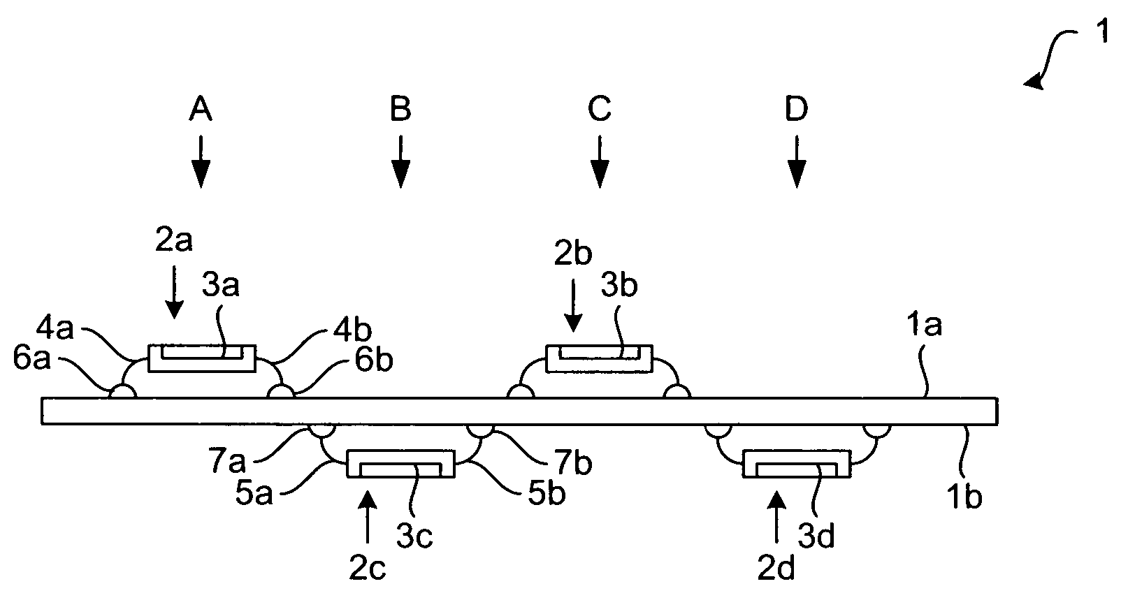
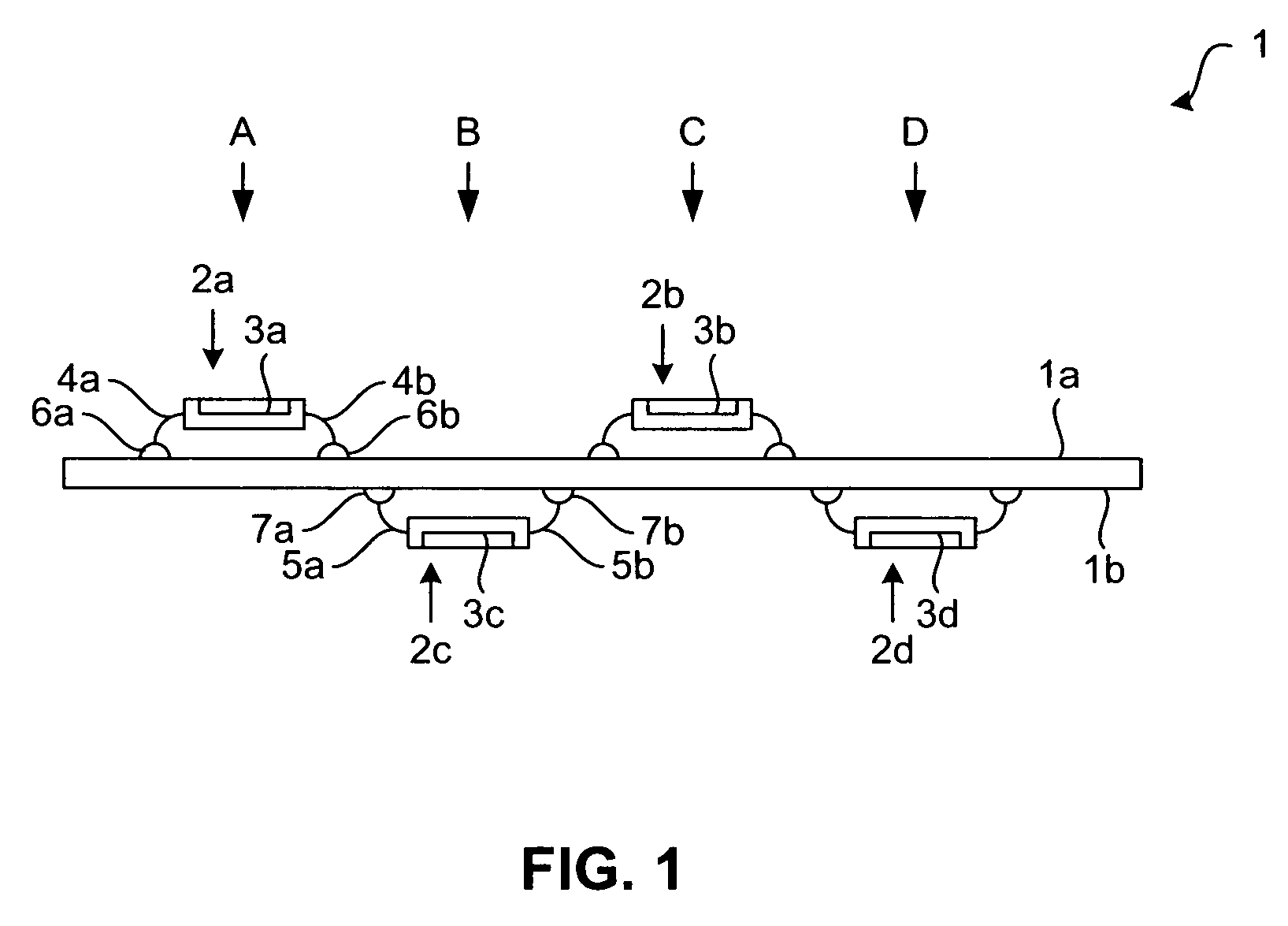
[0039]FIG. 1 shows a side view of a section of a printed circuit board (PCB) 1, as well as several power-dissipating components in the form of packages 2a, 2b, 2c, 2d containing devices in the form of integrated circuits 3a, 3b, 3c, 3d, according to a first embodiment of the invention. The integrated circuits can be mounted onto the packages 2a-2d by several known techniques like soldering, flip-chiping and so on. The packages 2a-2d can also or exclusively contain other heat-dissipating electrical or electronic devices like (arrays of) resistors and / or capacitors etc. and are not limited to a certain type of heat-dissipating device. The packages / housings 2a-2d are formed of suitable material like ceramics, plastics, composites etc. or a mixture thereof.

[0040] The integrated circuits 3a-3d may be respective analog and / or digital circuits, and / or memory devices (PLAs, PALs, ROMs, RAMs, etc.) and so on.

[0041] Thereby, respective contacts of the integrated circuits 3a-3d are—e.g. by m...


PUM


Abstract

The invention refers to an electronic system, comprising several power-dissipating components, and a circuit board, wherein said power-dissipating components are mounted both to a top side and a bottom side of said circuit board. Further, the invention refers to method for mounting power-dissipating components onto a circuit board, comprising the steps of (a) determining the thermal behavior of said power-dissipating components; and (b) determining, in accordance thereto, the placement of said power-dissipating components on both a top side and a bottom side of said circuit board.

Description

CROSS REFERENCE TO RELATED APPLICATIONS [0001] This application claims benefit to U.S. Provisional Application No. 60 / 577,213 filed on Jun. 7, 2004, and titled “Thermally Improved Placement of Electronic Components” which is incorporated by reference herein in its entirety.BACKGROUND OF THE INVENTION [0002] 1. Field of the Invention [0003] The invention relates to an electronic system, comprising several power-dissipating components, in particular packages containing integrated circuits, and to a method for mounting these components onto a circuit board. [0004] 2. Background Art [0005] Circuit boards typically comprise several power-dissipating components (e.g., integrated circuits like processing units, controllers etc., and / or resistors and so on) mounted thereon. Especially integrated circuits (e.g., analog and / or digital circuits, memory devices (PLAs, PALs, ROMs, RAMs, etc.) in the form of silicon chips) can be loaded into and electrically contacted with special housings (“pack...

Claims


Application Information

Patent Timeline
IPC IPC(8): H05K1/18H05K1/02H05K7/20
CPCH05K1/0203H05K1/181H05K2201/09709H05K2201/10477H05K2201/10689H05K2203/1572H01L2924/0002H01L2924/00Y02P70/611Y02P70/50
Inventor VERBIST, RUDI
Owner AVAGO TECH INT SALES PTE LTD
Learn More