Detection circuit having an adaptive threshold

Active Publication Date: 2005-02-15
TEXAS INSTR INC
View PDF1 Cites 1 Cited by
  • Summary
  • Abstract
  • Description
  • Claims
  • Application Information

AI Technical Summary

Benefits of technology

This and other objects and features are provided, in accordance with one aspect of the invention by a voltage detector circuit comprising a comparator having a first input coupled to a first voltage source having a first voltage and a second input coupled to a second voltage source having a second voltage to be compared to the first voltage source. A resistance is coupled in series with the second input. A variable current source reference is coupled to the resistance to draw a refer

Problems solved by technology

A weakness of the circuit shown in FIG. 1A is that in order to have an accurate threshold voltage which is temperature compensated, the current drawn by the comparator circuit and the reference ge

Method used


Image

  • Detection circuit having an adaptive threshold
  • Detection circuit having an adaptive threshold
  • Detection circuit having an adaptive threshold

Examples


Example

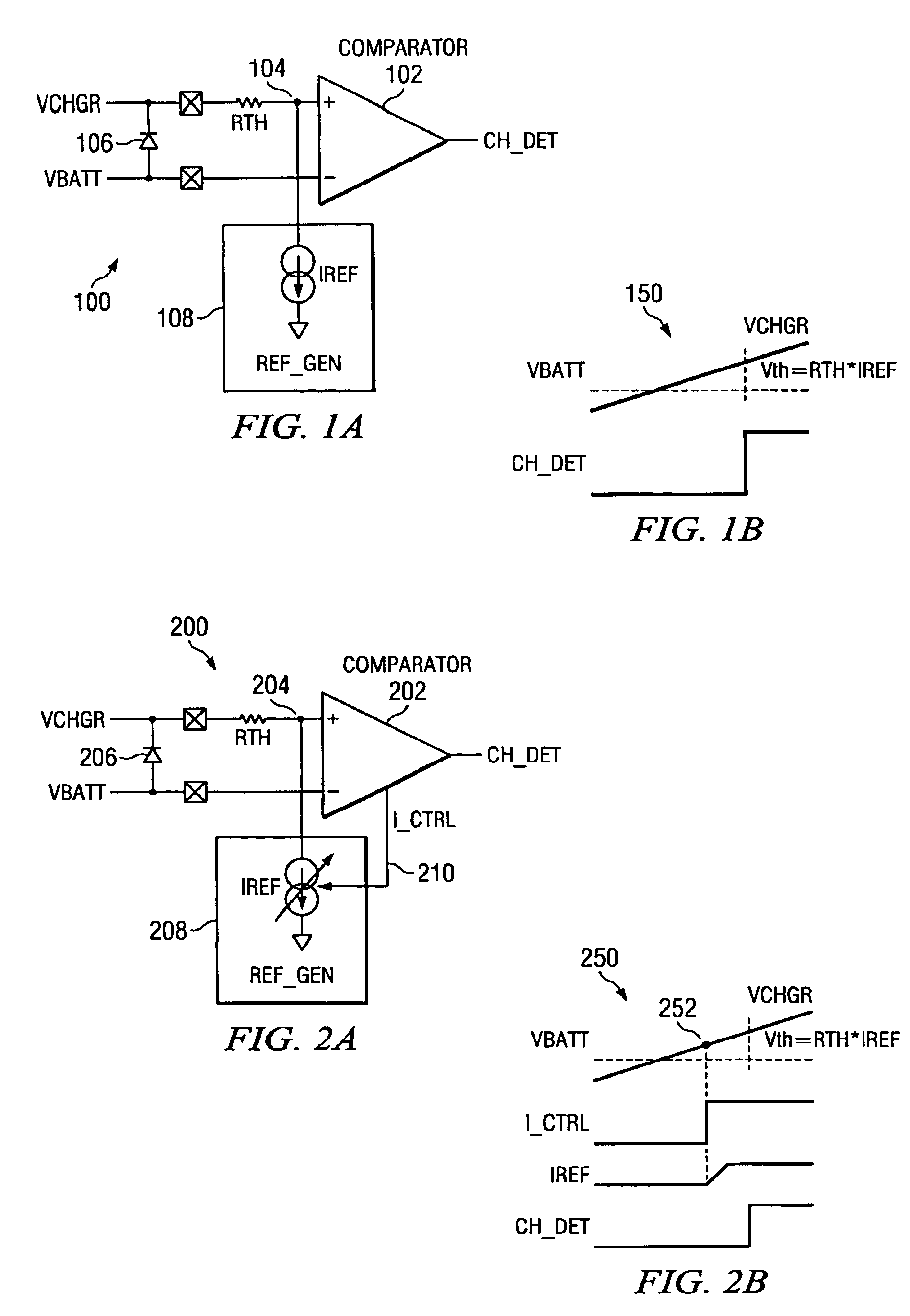
FIG. 2A shows a block diagram of the voltage detector according to the present invention generally as 200. The battery charger voltage VCHRG is applied to the non-inverting input of comparator 202 via series resistance RTH. The battery voltage VBATT is applied to the inverting terminal of comparator 202. Diode 206 represents the back gate diode for the FET. A current reference generator 208 generates a current reference IREF which is drawn through resistance RTH from node 204 to the reference potential. In the circuit shown in FIG. 2A, the reference generator 208 generates a reference current which has two levels, the level of reference current generated by the reference signal generator 208 being dependent upon a control signal I_CTRL output from the comparator on line 210.

FIG. 2B represents the waveforms for the apparatus in FIG. 2A as the input voltage VCHRG is raised past the battery voltage VBATT. As can be seen from these waveforms, the signal IREF has two distinct levels and ...


PUM


Abstract

A voltage detection circuit utilizes a comparator to compare first and second input voltages to generate a control signal when the difference between the first and second input voltages exceeds a threshold. The threshold voltage is generated by injecting a known current into a resistance in series with one of the inputs. The voltage detection circuit utilizes a first level of injected current when the input differential voltage differs from the threshold by a predetermined voltage level. The injected current rises to a second level as the second input voltage approaches the first input voltage in order to obtain a more accurate voltage comparison.

Description

TECHNICAL FIELD OF THE INVENTIONThis invention relates to a voltage detector and more specifically to a voltage detector for a battery powered device, such as a cellular telephone.BACKGROUND OF THE INVENTIONHigh energy rechargeable batteries have enabled an explosion in small handheld electronic devices such as cellular telephones, PDAs, and two way messaging devices. In these devices, the charging circuit for the rechargeable battery is typically located outside of the device in order to avoid penalizing the device by the size, weight and heat generated by the charging circuit. A cable from the charging circuit will typically plug into a connector on the portable device. Typically a pair of back-to-back-FETs are utilized to permit the battery to be charged, but avoid the possibility of discharging the battery when charger is inactive. An inactive charger may act as a load on the battery. These FETs must be able to withstand the surges associated with battery charging and therefore ...

Claims


Application Information

Patent Timeline
IPC IPC(8): H01M10/46H01M10/42H02J7/00H01M10/44G01R19/165
CPCG01R19/16542
Inventor XI, XIAOYURODRIGUEZ, CHARLES
Owner TEXAS INSTR INC
Why Eureka
Try Eureka