Glue dispensing device and glue dispensing method

Inactive Publication Date: 2014-01-30
HON HAI PRECISION IND CO LTD
View PDF1 Cites 3 Cited by
  • Summary
  • Abstract
  • Description
  • Claims
  • Application Information

AI Technical Summary

Benefits of technology

The present patent relates to a glue dispensing device and method for applying glue to a lens module during assembly. The device includes a glue tube and a ball, which can be opened and closed to control the flow of glue. The device can be fixed on a robotic arm and used to apply glue to the lens module while it rotates. The technical effect of this invention is to provide a more efficient and precise method for applying glue to the lens module during assembly, reducing the risk of contamination and ensuring a better quality product.

Problems solved by technology

However, the glue may drip from the small needles when not in use and may contaminate the lens module.

Method used


Image

  • Glue dispensing device and glue dispensing method
  • Glue dispensing device and glue dispensing method
  • Glue dispensing device and glue dispensing method

Examples


first embodiment

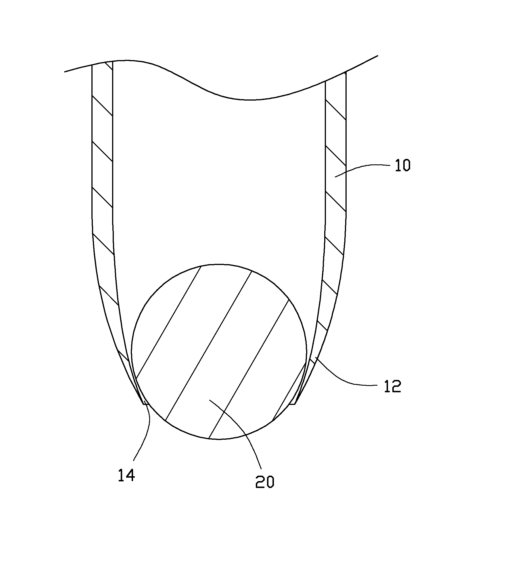
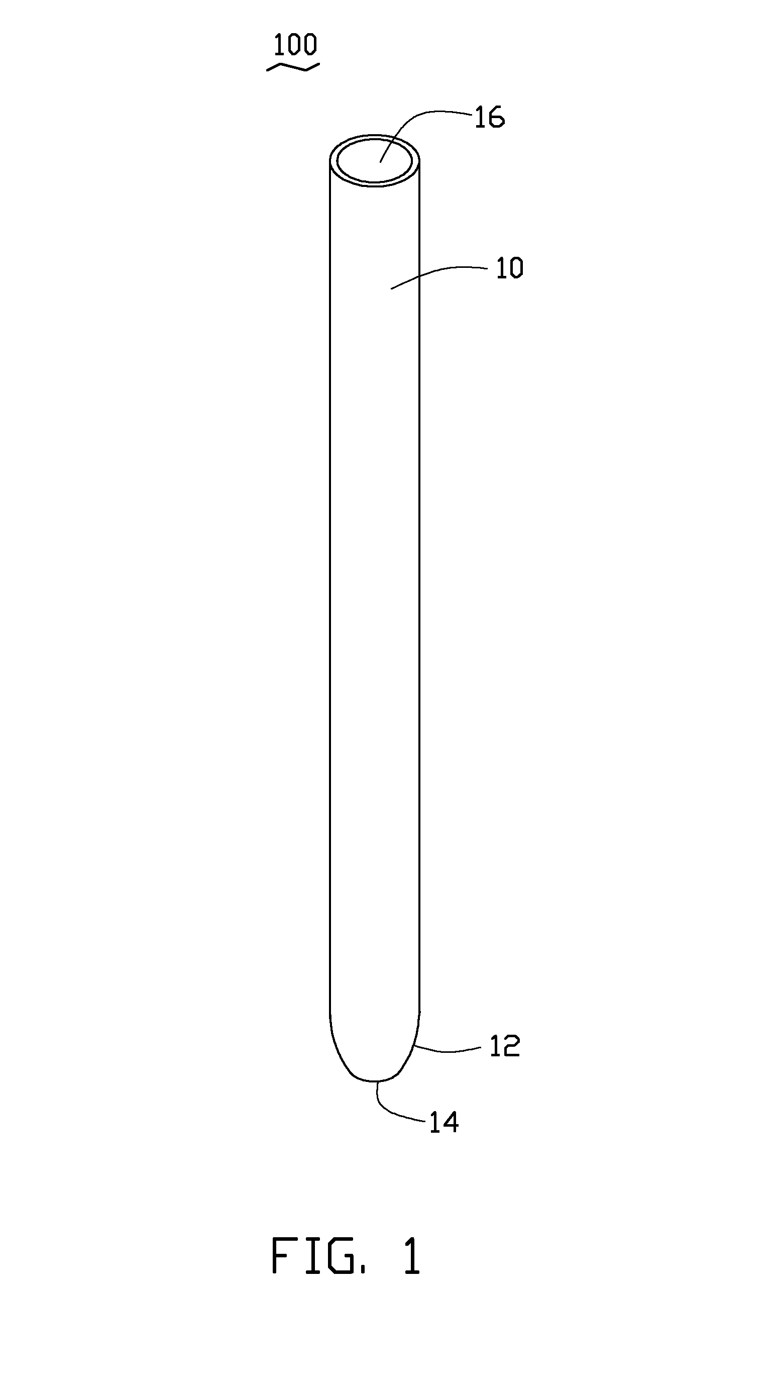
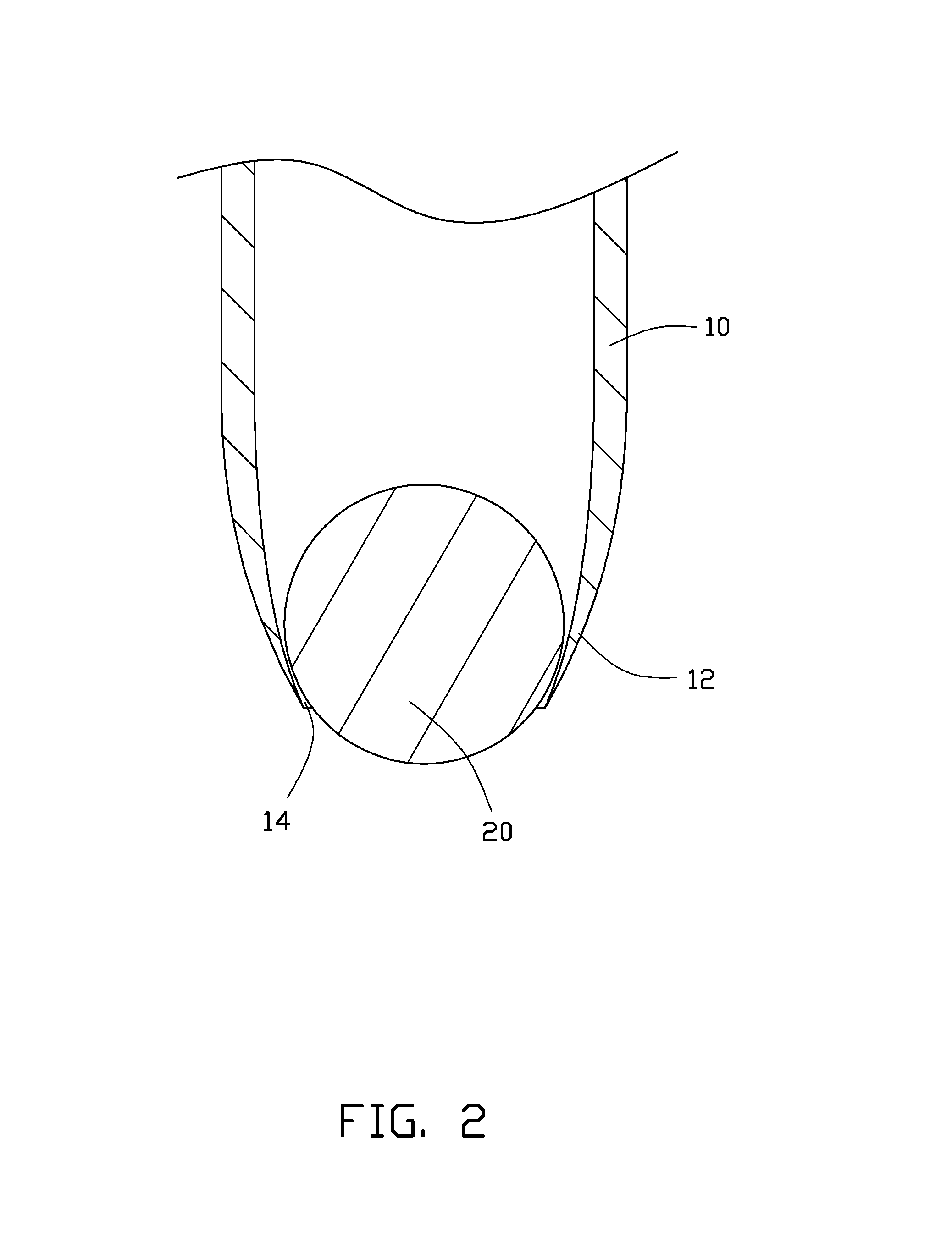
[0012]FIGS. 1 and 2 show a glue dispensing device 100 according to a The glue dispensing device 100 includes a glue tube 10 and a ball 20. The glue tube 10 includes a glue outflow end 12 and a glue inflow end 16 opposite to the glue outflow end 12. The glue outflow end 12 is a taped end and defines a round opening 14. The ball 20 is movably contained in the glue tube 10 at the glue outflow end 12. A diameter of the ball 20 is greater than a diameter of the round opening 14. The ball 20 closes the round opening 14. The round opening 14 can be opened by pushing the ball 20 into the glue tube 10. The glue inflow end 16 is used for injecting glue into the glue tube 10. The diameter of the ball 20 is smaller than a diameter of the glue inflow end 16. In this embodiment, the ball 20 is made of metal.

second embodiment

[0013]FIGS. 3 to 5 show a glue dispensing method using the glue dispensing device 100 accordingly to a The glue dispensing method includes steps described below.

[0014]In step 1, a unfinished lens module 60 including a barrel 30, a lens 40 and a spacer 50 is provided. The lens 40 and the spacer 50 are received in the barrel 30. The spacer 50 can be a spacer ring or a filter. The spacer 50 includes a ring shaped projection 51 spaced from the barrel 30. The spacer 50 and the barrel 30 cooperatively form a glue receiving groove 52.

[0015]In step 2, a rotary platform 70 is provided to carry the lens module 60.

[0016]In step 3, the glue dispensing device 100 is provided. The glue dispensing device 100 receives glue 101 in the glue tube 10 and is fixed on a robotic arm 80.

[0017]In step 4, the glue dispensing device 100 is driven by the robotic arm 80 to make the glue outflow end 12 enter into the glue receiving groove 52. The bottom surface of the glue receiving groove 52 pushes the ball 20...


PUM


Abstract

A glue dispensing device includes a glue tube and a ball. The glue tube includes a taped glue outflow end. The glue outflow end defines a round opening. The ball is movably received in the glue tube, a diameter of the ball is greater than a diameter of the round opening. The ball closes the round opening when not being pressed, and opens the round opening when being pressed.

Description

BACKGROUND[0001]1. Technical Field[0002]The present disclosure relates to a glue dispensing device and a glue dispensing method using the glue dispensing device.[0003]2. Description of Related Art[0004]During a lens module assembly process, glue is required to fix an optical element firmly in a barrel. Small needles are generally employed to inject and dispense the glue as the lens module becomes more compact. However, the glue may drip from the small needles when not in use and may contaminate the lens module.[0005]Therefore, it is desired to provide a glue device and a glue method which can overcome the above mentioned shortcomings.BRIEF DESCRIPTION OF THE DRAWINGS[0006]FIG. 1 is a schematic, isometric view of a glue dispensing device according to a first embodiment.[0007]FIG. 2 is an enlarged, sectional, partial view of the glue dispensing device of FIG. 1.[0008]FIG. 3 is a schematic view showing a glue dispensing method according to a second embodiment.[0009]FIG. 4 is another sc...

Claims


Application Information

Patent Timeline
IPC IPC(8): B05C1/00
CPCB05C1/00B05C5/0216B05C5/0225G02B7/025
Inventor WANG, CHIEN-CHUN
Owner HON HAI PRECISION IND CO LTD
Why Eureka
Try Eureka