Methods and systems for a rail vehicle including a source of gaseous natural gas

Active Publication Date: 2014-02-06
GE GLOBAL SOURCING LLC
View PDF3 Cites 27 Cited by
  • Summary
  • Abstract
  • Description
  • Claims
  • Application Information

AI Technical Summary

Problems solved by technology

Such an interface, however, requires suitable cryogenic hosing, cryogenic coupling components, and associated design constraints and maintenance requirements.
Transferring LNG across such an interface also creates the potential for LNG leaks.
However, as with transferring LNG across an interface, this configuration requires additional insulated hosing and coupling components that present design challenges and risks.
Additio

Method used


Image

  • Methods and systems for a rail vehicle including a source of gaseous natural gas
  • Methods and systems for a rail vehicle including a source of gaseous natural gas
  • Methods and systems for a rail vehicle including a source of gaseous natural gas

Examples


Embodiment Construction

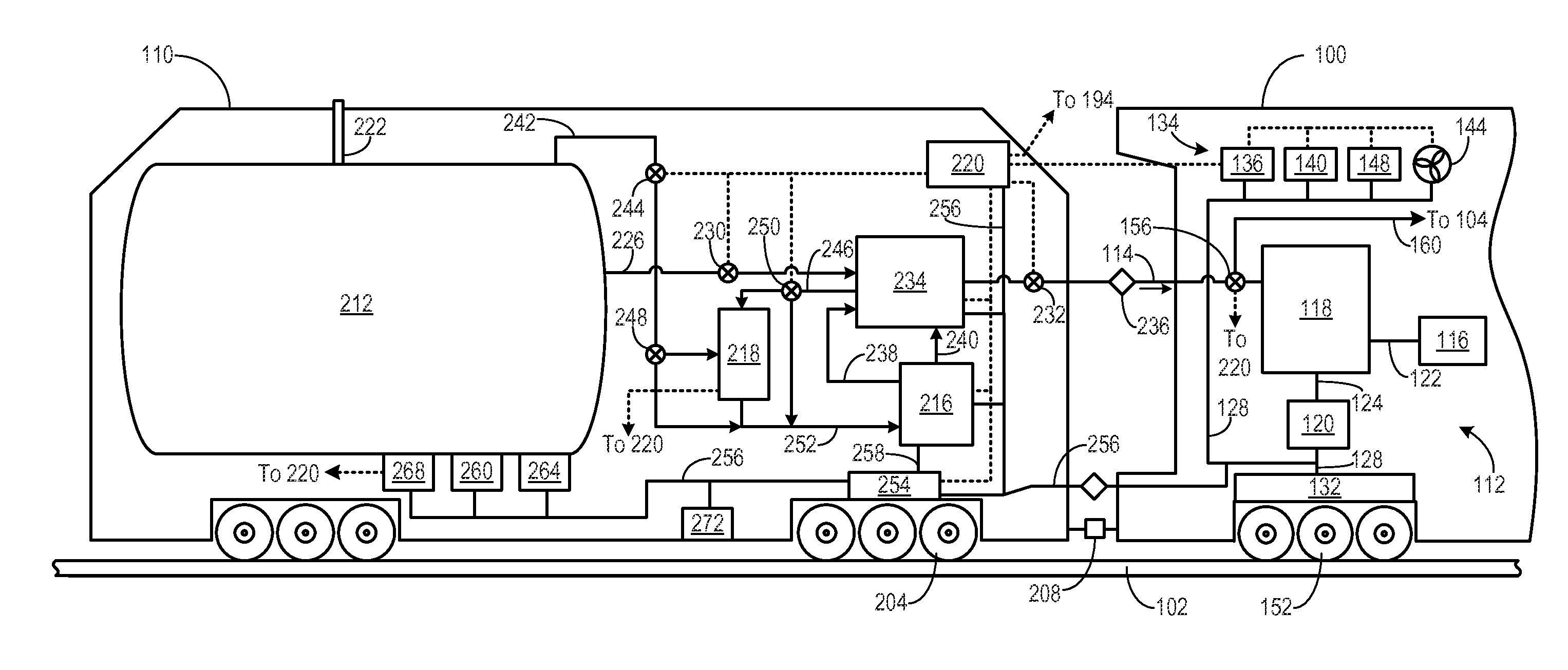
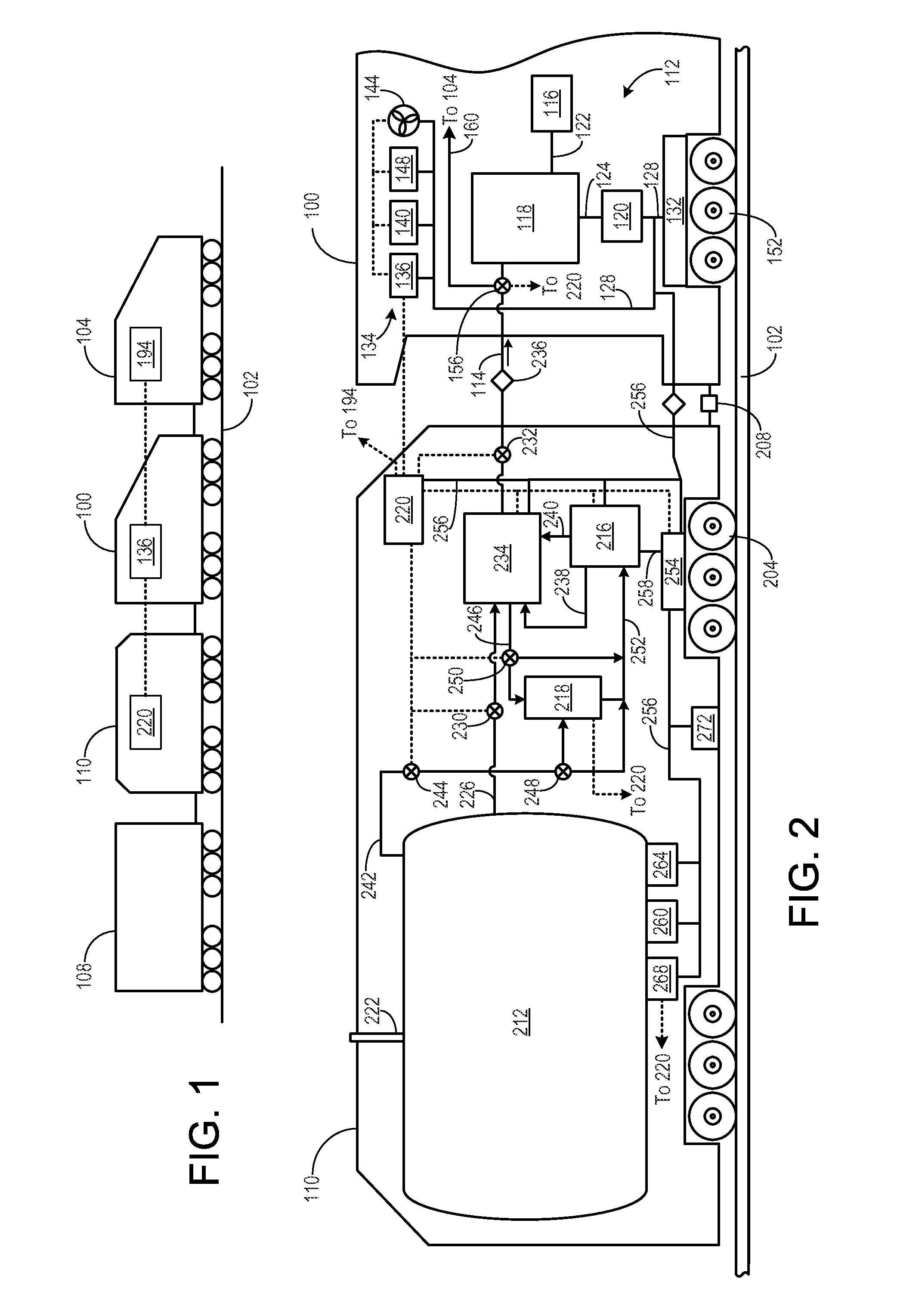
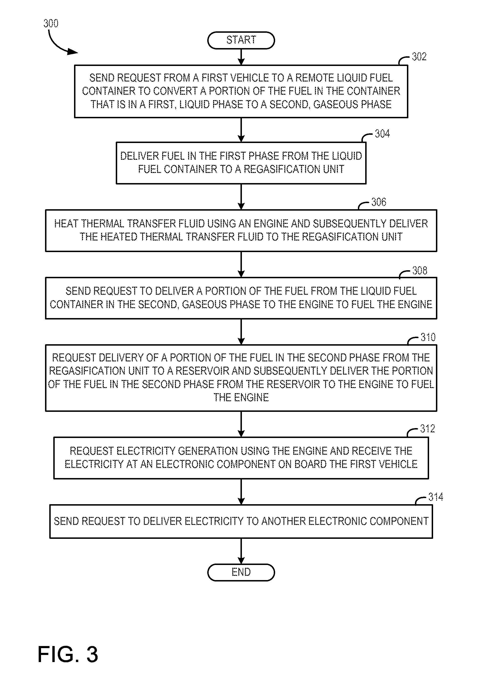
[0018]The following description relates to various embodiments of controlling a rail vehicle. Specifically, the rail vehicle may receive gaseous natural gas to power a multi-fuel engine on board the rail vehicle and / or electrical energy to power electronic components on board the rail vehicle. The rail vehicle may receive the gaseous natural gas and electrical energy from a remote liquid fuel container (e.g., a liquid fuel container located off-board the rail vehicle) and a natural gas-fueled engine, respectively, both the liquid fuel container and the natural gas-fueled engine being off board the rail vehicle. In one example, the liquid fuel container and the natural gas-fueled engine are on board a fuel tender coupled to the rail vehicle, as shown at FIGS. 1-2. As described in more detail below, in some embodiments the rail vehicle may send signals or requests to the fuel tender to store liquefied natural gas (LNG) and convert the LNG to gaseous natural gas. A natural gas-fueled e...


PUM


Abstract

Various methods and systems are provided for supplying gaseous natural gas to a rail vehicle. In one embodiment, a method of receiving fuel for use by a first vehicle comprises sending a request from the first vehicle to a remote liquid fuel container to convert a portion of the fuel in the liquid fuel container that is in a first, liquid phase from the first, liquid phase to a second, gaseous phase.

Description

CROSS-REFERENCE TO RELATED APPLICATIONS[0001]This application claims priority to U.S. Provisional Application No. 61 / 678,191, filed Aug. 1, 2012, which is hereby incorporated by reference herein in its entirety.FIELD[0002]Embodiments of the subject matter disclosed herein relate to a rail vehicle, and related methods for supplying fuel to an engine of the rail vehicle.BACKGROUND[0003]Locomotives (or other vehicles) typically include a prime mover that is powered by a fuel source to generate mechanical energy. In one example of a locomotive, mechanical energy generated by the prime mover may be converted to electrical energy that is used to power traction motors and other components and systems of the locomotive. In some examples, the prime mover may be a combustion engine that is fueled by diesel, gasoline, or other liquid petroleum distillates. In other examples the engine may additionally or alternatively utilize a gaseous fuel, such as natural gas.[0004]In light of its favorable ...

Claims


Application Information

Patent Timeline
IPC IPC(8): F17C7/00
CPCF17C7/00B61C17/02B61C17/12F17C1/00F17C13/00F17C2203/0391F17C2221/033F17C2223/0161F17C2223/033F17C2225/0123F17C2225/035F17C2227/0332F17C2227/0393F17C2250/01F17C2250/043F17C2250/0439F17C2260/044F17C2265/031F17C2265/037F17C2265/066F17C2265/07F17C2270/0173B61C5/00B61C7/04Y02T30/00
Inventor BILLIG, RONALD GENESHAH, TARAL
Owner GE GLOBAL SOURCING LLC
Why Eureka
Try Eureka