Method and system for generating a displacement map from a normal map

a displacement map and normal map technology, applied in the field of computer graphics, can solve the problems of revealing the coarseness of the object's underlying geometry, unable to accurately produce silhouettes, shadows, occlusions, etc., and existing graphic assets typically lack the geometric information (e.g. depth information) needed, and achieves the effect of quick and inexpensive conversion and more detailed geometric features

Active Publication Date: 2014-02-06
NVIDIA CORP
View PDF3 Cites 14 Cited by
  • Summary
  • Abstract
  • Description
  • Claims
  • Application Information

AI Technical Summary

Benefits of technology

[0009]One advantage of the disclosed technique is that the normal maps of existing graphic assets can be quickly and inexpensively converted into displacement maps, enabling existing graphic assets to be used in systems capable of performing tessellation of incoming geometries and displacing the vertices of the resulting graphic primitives to generate more detailed geometric features.

Problems solved by technology

Consequently, bump mapping cannot accurately produce silhouettes, occlusion, and shadows, revealing the coarseness of the object's underlying geometry.
However, as discussed above, many existing graphic assets were designed to be used with techniques (e.g., bump mapping) that do not affect object geometries and were not designed or intended to be used with tessellation.
Consequently, existing graphic assets typically lack the geometric information (e.g., depth information) needed to generate realistic and detailed object geometries with the additional vertices created during tessellation.
Moreover, the process of converting existing graphic assets to take advantage of tessellation, as well as other sophisticated geometric processing techniques included in current graphics APIs, is time-consuming and expensive.
Thus, given the financial risks and uncertain return on investment, few developers are willing to expend the resources necessary to update existing graphic assets to include the required geometric information.

Method used


Image

  • Method and system for generating a displacement map from a normal map
  • Method and system for generating a displacement map from a normal map
  • Method and system for generating a displacement map from a normal map

Examples


Embodiment Construction

[0017]In the following description, numerous specific details are set forth to provide a more thorough understanding of the present invention. However, it will be apparent to one of skill in the art that the present invention may be practiced without one or more of these specific details.

System Overview

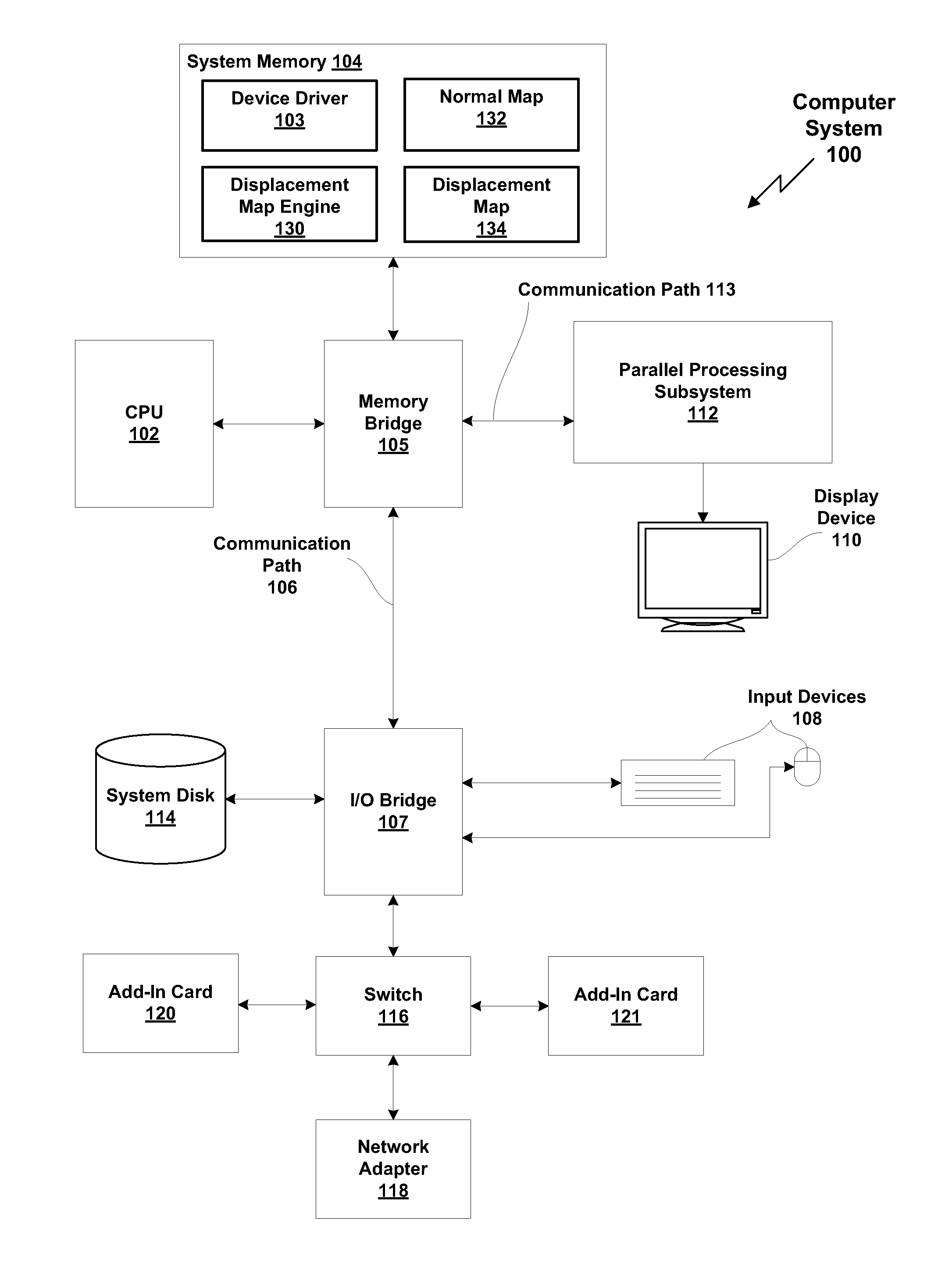
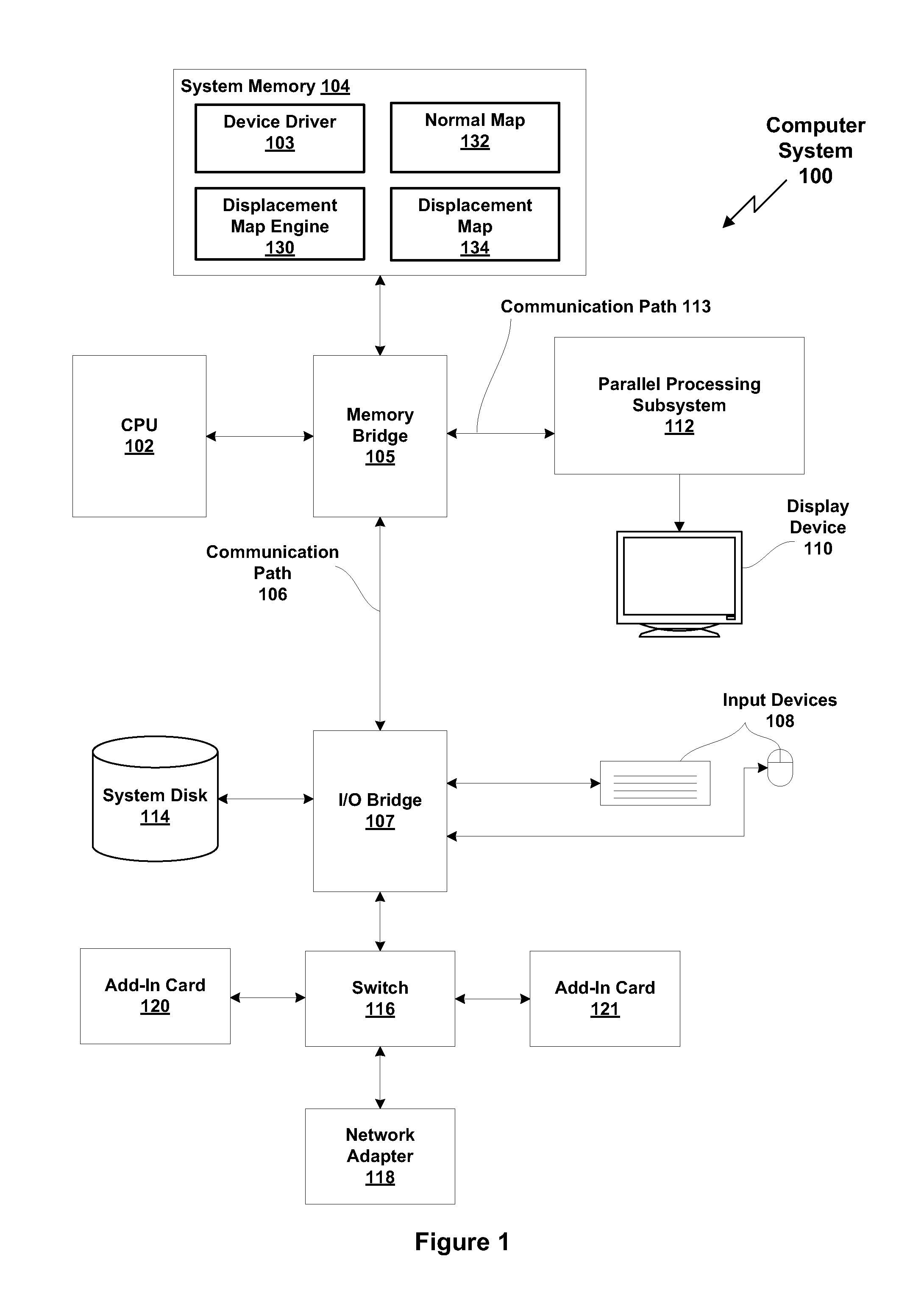
[0018]FIG. 1 is a block diagram illustrating a computer system 100 configured to implement one or more aspects of the present invention. Computer system 100 includes a central processing unit (CPU) 102 and a system memory 104 communicating via an interconnection path that may include a memory bridge 105. The system memory 104 may be configured to store a device driver 103, a displacement map engine 130, a normal map 132, and a displacement map 134. The CPU 102 may be configured to execute the displacement map engine 130 to process a normal map 132 and generate a displacement map 134. Memory bridge 105, which may be, e.g., a Northbridge chip, is connected via a bus or other communicati...


PUM


Abstract

One embodiment of the present invention sets forth a technique for generating a displacement map. The technique involves receiving a normal map which includes one or more normal vectors associated with a texture map, processing the one or more normal vectors to a calculate one or more depth difference vectors associated with the texture map, and generating one or more rays associated with a first texel of the texture map, where each of the one or more rays associated with the first texel traverses one or more other texels of the texture map. The technique further involves calculating, for each of the one or more rays associated with the first texel, relative depths of each of the one or more other texels traversed by the ray based on each of the depth difference vectors that correspond with the one or more other texels traversed by the ray, determining a displacement value associated with the first texel based on the relative depths calculated for the one or more rays, and storing the displacement value in a displacement map.

Description

BACKGROUND OF THE INVENTION[0001]1. Field of the Invention[0002]The present invention generally relates to computer graphics, and, more specifically, to a method and system for generating a displacement map from a normal map.[0003]2. Description of the Related Art[0004]Conventionally, graphics processing systems have relied on techniques such as bump mapping to produce realistic lighting effects in computer-generated images. In bump mapping, the surface normals of a polygon mesh are calculated and stored in a normal map. During rendering, the normal map is used to perform lighting calculations, which are applied to a lower-resolution version of the polygon mesh. In this way, geometric details present on the original polygon mesh can be simulated and applied to a lower-resolution polygon mesh in order to conserve computational resources. Although bump mapping is capable of simulating the lighting of the original object, the underlying geometry of the lower-resolution object is unchan...

Claims


Application Information

Patent Timeline
Patent Type & Authority Applications(United States)
IPC IPC(8): G09G5/00
CPCG09G5/363G06T15/04G09G2352/00G09G2360/10
Inventor DMITRIEV, KIRILL
Owner NVIDIA CORP
Why Eureka
Try Eureka