Shutdown strategy to avoid carbon corrosion due to slow hydrogen/air intrusion rates

a hydrogen/air intrusion rate and carbon corrosion technology, applied in the field of hydrogen fuel cells, can solve the problems of short distance, rapid corrosion of fuel cell carbon substrates and catalyst supports, and degraded fuel cell performance, so as to maximize the durability of the fuel cell system, not sacrificing the hydrogen-hydrogen shutdown strategy, and minimizing carbon corrosion

Active Publication Date: 2014-02-06
GM GLOBAL TECH OPERATIONS LLC
View PDF4 Cites 4 Cited by
  • Summary
  • Abstract
  • Description
  • Claims
  • Application Information

AI Technical Summary

Benefits of technology

[0009]Concordant and consistent with the present invention, a fuel cell system and a method for minimizing carbon corrosion in the fuel cell system, wherein the system and the method maximize the durability of the fuel cell system while not sacrificing a hydrogen-hydrogen shutdown strategy, has surprisingly been discovered.
[0011]The invention also provides methods for minimizing carbon corrosion in a fuel cell system.

Problems solved by technology

The hydrogen-air front is known to degrade fuel cell performance.
In particular, the presence of both hydrogen and air on the anode results in a localized short between a portion of the anode that sees hydrogen and a portion of the anode that sees air.
The localized short causes a reversal of current flow and increases the cathode interfacial potential, resulting in a rapid corrosion of the fuel cell carbon substrates and catalyst supports.
However, if air leaks into the cathode while hydrogen is still present, a stagnant hydrogen-air front can form on the anode which will cause carbon corrosion on the cathode electrode.
Unfortunately, the gas may condense on valves and other critical moving parts, and then freeze.
The frozen condensation can render the valve (or other critical component) inoperative during startup, thereby leading to increased damage to cells upon startup and / or a failed freeze start.

Method used


Image

  • Shutdown strategy to avoid carbon corrosion due to slow hydrogen/air intrusion rates
  • Shutdown strategy to avoid carbon corrosion due to slow hydrogen/air intrusion rates
  • Shutdown strategy to avoid carbon corrosion due to slow hydrogen/air intrusion rates

Examples


Embodiment Construction

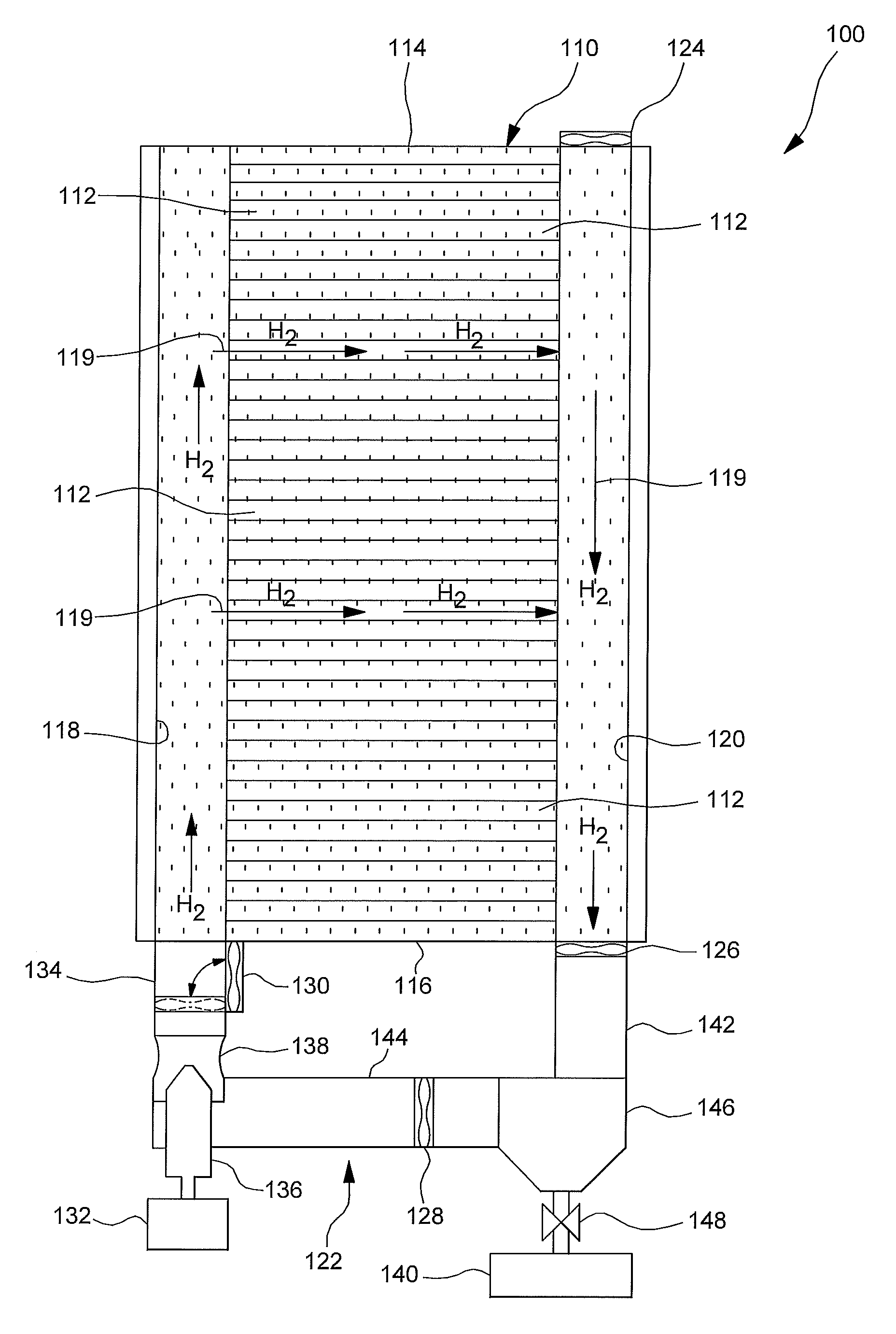
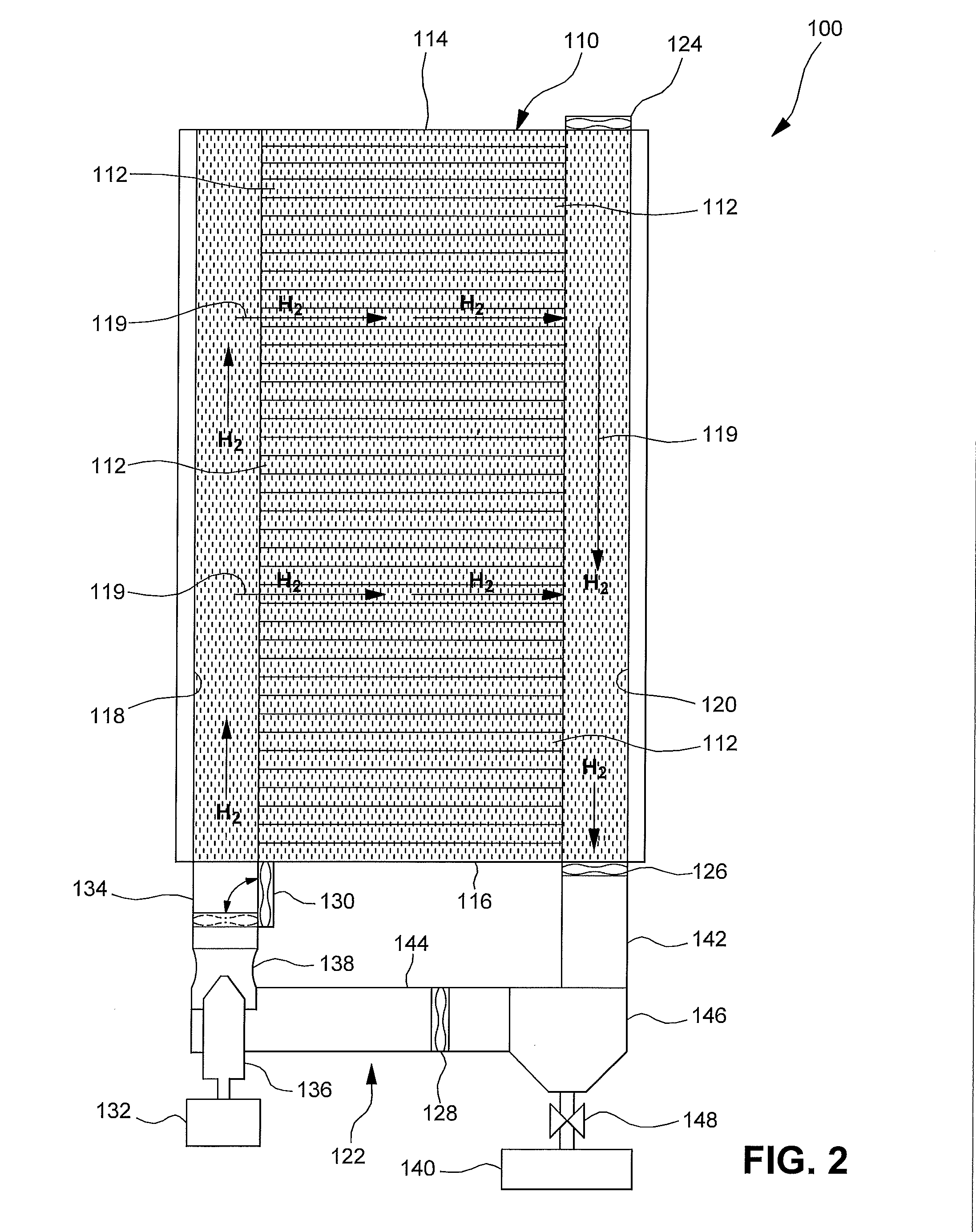
[0019]The following detailed description and appended drawings describe and illustrate various embodiments of the invention. The description and drawings serve to enable one skilled in the art to make and use the invention, and are not intended to limit the scope of the invention in any manner. In respect of the methods disclosed, the steps presented are exemplary in nature, and thus, the order of the steps is not necessary or critical.

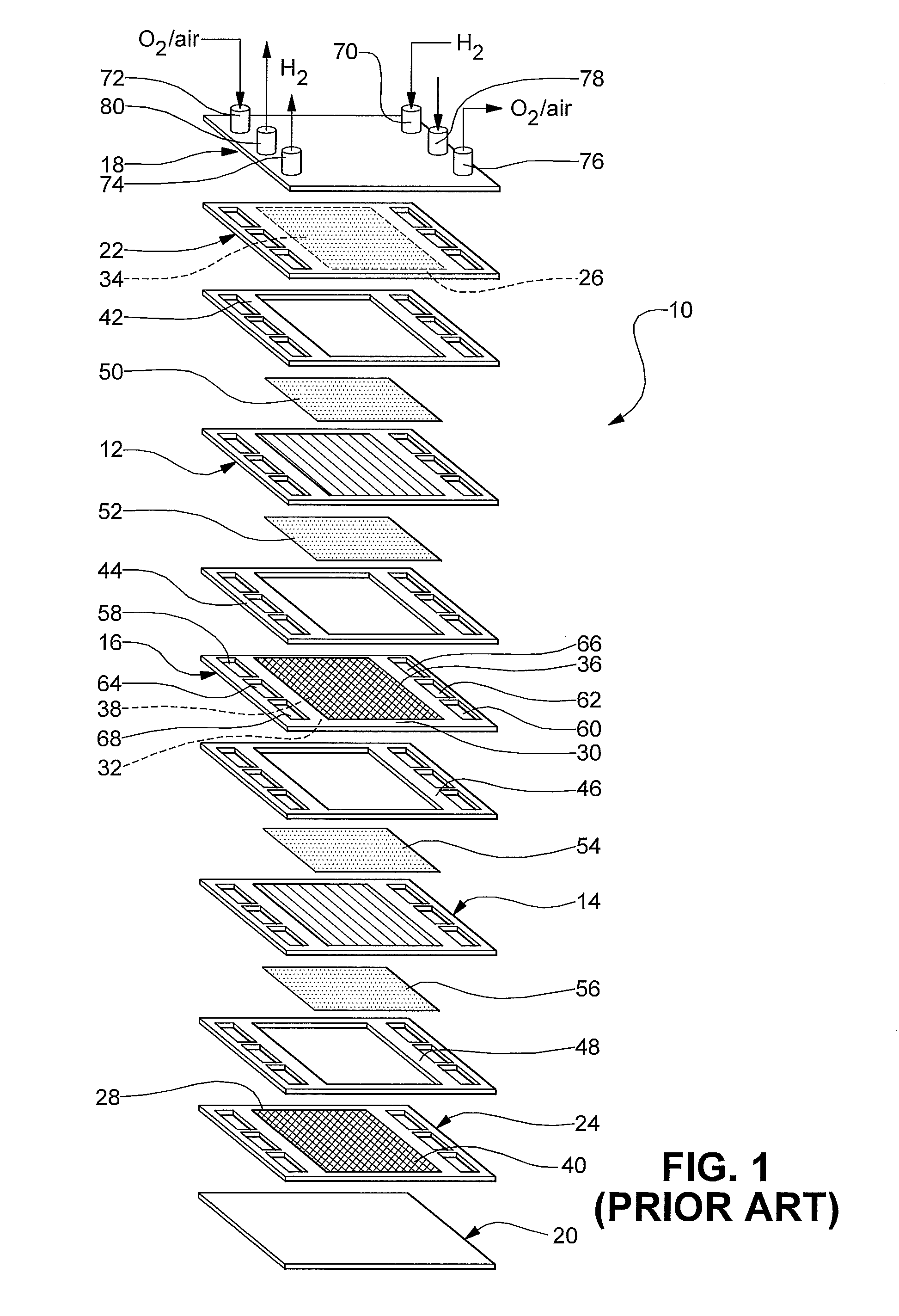
[0020]For simplicity, only a two-cell stack (i.e. one bipolar plate) is illustrated and described in FIG. 1, it being understood that a typical fuel cell stack will have many more such cells and bipolar plates.

[0021]FIG. 1 illustrates a PEM fuel cell stack 10 according to the prior art. The fuel cell stack 10 includes a pair of membrane electrode assemblies (MEAs) 12, 14 separated by an electrically conductive bipolar plate 16. The MEAs 12, 14 and the bipolar plate 16 are stacked between a pair of clamping plates 18, 20 and a pair of unipolar end plat...


PUM


Abstract

A fuel cell system including a fuel cell stack having a plurality of fuel cells, each of the fuel cells including an electrolyte membrane disposed between an anode and a cathode, an anode supply manifold in fluid communication with the anodes of the fuel cells, the anode supply manifold providing fluid communication between a source of hydrogen and the anodes, an anode exhaust manifold in fluid communication with the anodes of the fuel cells, and a fan in fluid communication with the anodes of the fuel cells, wherein the fan controls a flow of fluid through the anodes of the fuel cells after the fuel cell system is shutdown.

Description

CROSS-REFERENCE TO RELATED APPLICATIONS[0001]This application is a divisional of U.S. patent application Ser. No. 12 / 327,957 filed on Dec. 4, 2008. The entire disclosure of the above application is hereby incorporated herein by reference.FIELD OF THE INVENTION[0002]The invention relates to hydrogen fuel cells. More particularly, the invention is directed to a fuel cell system and a method for minimizing carbon corrosion in the fuel cell system.BACKGROUND OF THE INVENTION[0003]A fuel cell has been proposed as a clean, efficient and environmentally responsible power source for electric vehicles and various other applications. In particular, the fuel cell has been identified as a potential alternative for a traditional internal-combustion engine used in modern vehicles.[0004]A typical fuel cell is known as a proton exchange membrane (PEM) fuel cell. The PEM fuel cell includes three basic components: a cathode, an anode and an electrolyte membrane. The cathode and anode typically includ...

Claims


Application Information

Patent Timeline
Patent Type & Authority Applications(United States)
IPC IPC(8): H01M8/04
CPCH01M8/04223H01M8/04097H01M8/04228H01M8/2483Y02E60/50H01M8/242H01M8/04302H01M8/04303
Inventor GRESZLER, THOMAS A.ROBB, GARY M.SALVADOR, JOHN P.LAKSHMANAN, BALASUBRAMANIANGASTEIGER, HUBERT
Owner GM GLOBAL TECH OPERATIONS LLC
Why Eureka
Try Eureka