Device and method for aortic branched vessel repair

a technology of aortic branched vessels and devices, which is applied in the field of devices and methods for repairing aortic branched vessels, can solve the problems of life-threatening conditions of aortic aneurysms, high morbidity rates, and brain ischemia, and achieves reduced manipulation of aortic arch and resulting stroke in patients, and large margin of error in placement. , the effect of large apertur

Active Publication Date: 2014-02-06
BOLTON MEDICAL INC
View PDF6 Cites 38 Cited by
  • Summary
  • Abstract
  • Description
  • Claims
  • Application Information

AI Technical Summary

Benefits of technology

[0010]The aortic graft assembly of the invention does not require precise radial or longitudinal alignment in the aorta and permits approximate alignment, which is beneficial in reducing the manipulation of the aortic arch and resulting stroke in the patient. The claimed systems can be fully deployed before the surgeon completes the endovascular procedure by deployment of the first tunnel or second tunnel graft, unlike current aortic components that are in a “dogbone” configuration to guard against unintentional obstruction of the target ostium. The delivery device employed with the graft assembly aids in proper alignment of the assembly in the aorta by, for example, use of a curved guidewire catheter, proximal clasp and distal clasp.
[0011]The aortic assembly systems and methods of the invention can be employed to treat aortic aneurysms, such as aortic aneurysms at, near or around the arch of the aorta, or branches from the abdominal aorta (e.g., celiac artery, superior mesenteric artery and renal arteries). The aortic assembly systems of the invention have a relatively large aperture tapered into a tunnel graft that provides the surgeon with a relatively large margin of error in placement of the system, facilitates canulation and permits alignment of a single aperture for at least one blood vessel. Aortic assembly systems of the invention that include a tunnel graft having one aperture extending proximally with two openings permit for easy alignment in the aorta, particularly in regions of the aorta that branch to peripheral and major vessels. The size of the aperture allows blood to flow to target vessels during the procedure. The aortic graft assembly of the invention generally does not restrict blood flow acutely or chronically, in part, because of a relatively large diameter of the tunnel graft and the stent or stents supporting the tunnel graft.
[0012]Barbs in the interior of the tunnel grafts of the branched graft assembly have the advantage of securing connection of the tubular component to the tunnel graft. The telescoping ability of the graft assembly systems of the invention, for example, the length and different configurations of the tunnel graft, allow the tubular component to be positioned in-situ to ensure maximum use of a “landing zone” inside the target vessel. A relatively long tunnel length can ensure adequate overlap with the tubular component into the tunnel grafts to ensure a sufficient seal.
[0013]The delivery device of the invention also has the advantage of allowing the proximal end of the stent graft to be aligned perpendicular to the center line axis of the “landing zone.” This is of key concern when the landing zone is in Zone 0 (FIGS. 15, 16, 17) of the ascending aorta. When landing in this area much care must be taken to avoid accidental coverage of the coronary arteries, typically the left coronary artery.
[0014]Thus, the aortic graft assembly, delivery systems, and methods of the invention can be used to treat various aortic pathologies, including aortic aneurysms, penetrating atherosclerotic ulcers, dissections and, therefore, avoid complications and death consequent to life-threatening vascular conditions.

Problems solved by technology

Aortic aneurysms are life-threatening conditions.
For example, currently, if aortic devices are placed within the aortic arch in a manner that offsets the aperture for the left carotid artery, the artery can be occluded, which can result in ischemia to the brain.
Most surgical methods of treating aneurysms at or near the aortic arch generally involve sternotomy or thoracotomy and may require cardio-pulmonary bypass, often resulting in high morbidity rates.

Method used


Image

  • Device and method for aortic branched vessel repair
  • Device and method for aortic branched vessel repair
  • Device and method for aortic branched vessel repair

Examples


example 1

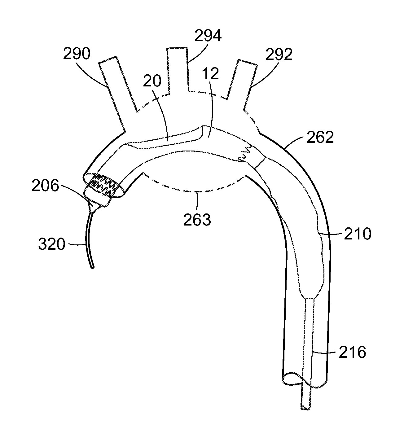
[0084]A 74 year old male with penetrating atherosclerotic ulcer (PAU) of the aorta located on the interior side of the thoracic arch at the level of the left common carotid was treated. A model of the patient's anatomy was made based on computer tomography (CT) scanning A right carotid to left carotid bypass was performed initially without ligating the left carotid. A tubular aortic component of an aortic graft assembly (46 mm−42 mm×80 mm) was deployed at the sinotubular junction. The ascending aorta of this patent had a graft diameter of about 44 mm. A tubular aortic component having a diameter of 46 / 42 mm×80 mm was employed to provide a smaller healthy neck. The proximal end of the tubular aortic component of the aortic graft assembly was released to optimize apposition with the wall of the ascending aorta.

[0085]A tunnel graft (46 mm−34 mm×220 mm) was used in the aortic graft assembly. The tunnel graft was 15 mm in diameter. The aperture of the tubular aortic component was 30 mm×3...

example 2

[0086]An 81 year old male with an aneurysm at the arch of the aorta was treated. A CT scan was employed to model the patient's anatomy. The thoracic aneurysm was in a region of the aortic arch and at least a portion of the descending aorta. The tunnel graft had a diameter of about 15 mm.


PUM


Abstract

An aortic graft assembly includes a tubular component that defines a wall aperture having a proximal end that extends perpendicular to a major longitudinal axis of the tubular aortic component, and a tunnel graft connected to the wall of the tubular aortic component and extending from the wall aperture toward a proximal end of the tubular aortic component. The method for delivery of the aortic graft assembly includes delivering the aortic graft assembly through the wall aperture and into interferring relation with the tunnel graft.

Description

RELATED APPLICATIONS[0001]This application is a continuation of International Application No. PCT / US2012 / 065622, filed on Nov. 16, 2012, which claims the benefit of U.S. Provisional Application No. 61 / 560,517, filed on Nov. 16, 2011. The entire teachings of the above applications are incorporated herein by reference.BACKGROUND OF THE INVENTION[0002]Aortic aneurysms are life-threatening conditions. Surgical interventions used to treat aortic aneurysms include endovascular repair by transluminal placement of one or more endografts across the longitudinal extent of the lesion. The endograft is placed in the aorta with the intention of bridging the aneurysmal sac to exclude it from the high-pressure of aortic blood flow, which can permit remodeling of the aortic wall in and around the aneurysm site. In certain regions of the aorta accurate placement of the endograft is critical to maintain blood flow to vessels branching from the aorta to minimize compromised blood flow to organs. For e...

Claims


Application Information

Patent Timeline
Patent Type & Authority Applications(United States)
IPC IPC(8): A61F2/07
CPCA61F2/07A61F2/966A61F2002/061A61F2002/067A61F2/89A61F2002/075A61F2220/0075A61F2002/821A61F2002/9665A61F2250/0098A61F2/954A61F2002/9505
Inventor ARBEFEUILLE, SAMUELCHRISTIAN, FLETCHERMANGUNO, JR., JOSEPH A.CANNING, JOHN C.
Owner BOLTON MEDICAL INC
Why Eureka
Try Eureka