Method for Calibrating a Real-Time Load-Pull System

a real-time load-pull system and real-time technology, applied in the field of incident and reflected waveform measurement, can solve the problems of significant measurement errors, high time-consuming s-parameter characterization of tuners, and the accuracy of real-time load-pull systems, so as to speed up the calibration procedure, simplify the calibration procedure of high-frequency load-pull systems, and reduce the effect of manipulation

Inactive Publication Date: 2009-07-09
VERSPECHT JAN +1
View PDF8 Cites 14 Cited by
  • Summary
  • Abstract
  • Description
  • Claims
  • Application Information

AI Technical Summary

Benefits of technology

[0012]It is the object of the present invention to simplify the calibration procedure of high-frequency load-pull systems as outlined above. With the novel method one eliminates the need to disconnect the tuner for the purpose of system calibration. This has several significant advantages when compared to the prior art. In the case where the tuners are connected and disconnected by hand, the novel method results in less manipulations. This has two advantages. Firstly, this speeds up the calibration procedure since manual connections and disconnections are time consuming. Secondly it decreases the chance of operator errors, thereby increasing the reliability of the calibration procedure. In case the tuners are connected and disconnected by means of automated switches, the novel method results in a measurement setup with fewer components since the switches can be eliminated. This has two advantages. Firstly, it results in a cost reduction of the measurement system. Secondly it decreases the chance of hardware failure, thereby increasing the reliability of the calibration procedure.

Problems solved by technology

This necessary a priori S-parameter characterization of tuners is very time consuming and often leads to significant measurement errors because of potential measurement inaccuracies.
One of the main challenges of any real-time load-pull system is the accuracy of the measured data.

Method used


Image

  • Method for Calibrating a Real-Time Load-Pull System
  • Method for Calibrating a Real-Time Load-Pull System
  • Method for Calibrating a Real-Time Load-Pull System

Examples


embodiment

Preferred Embodiment

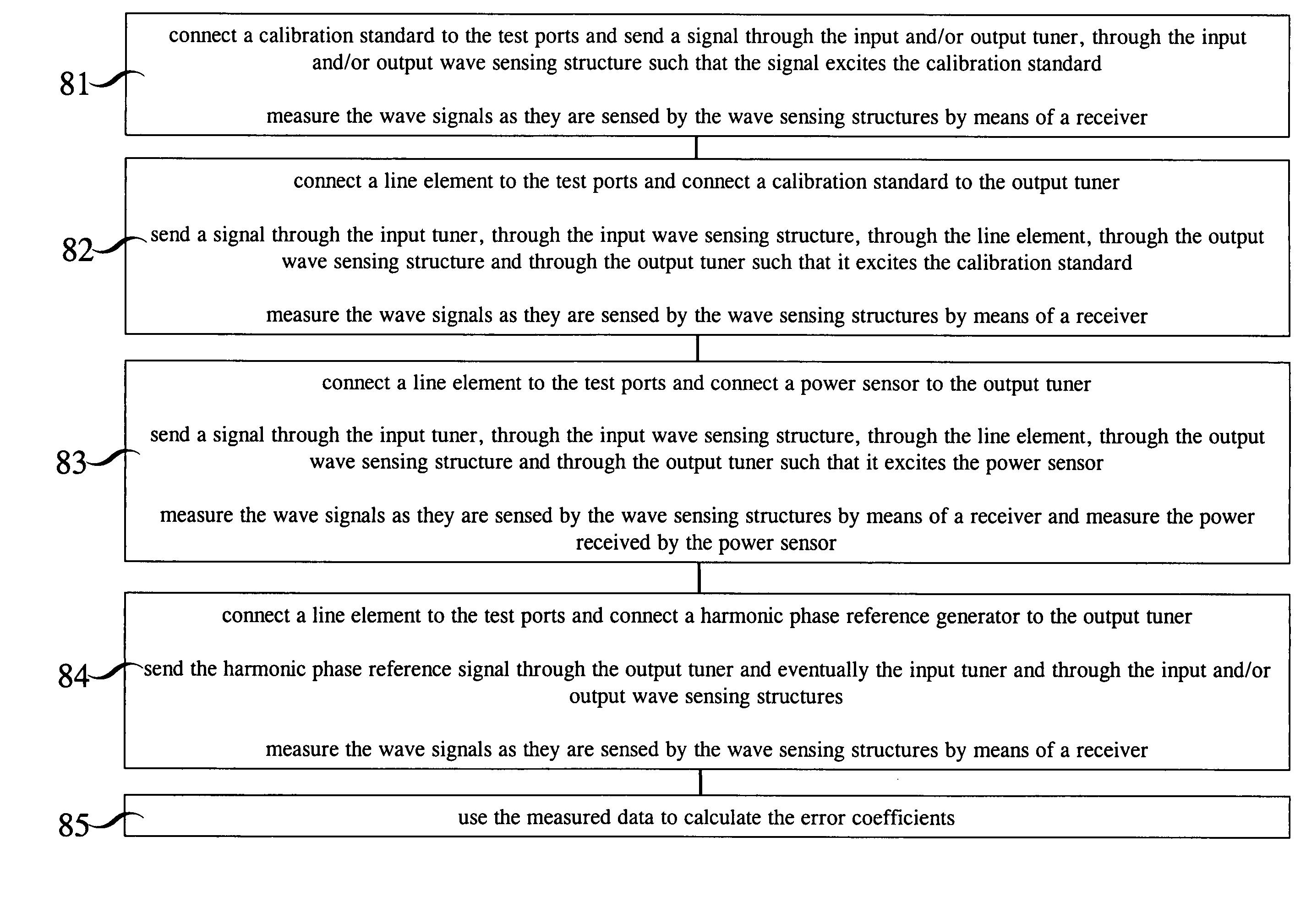
[0038]The invention was publicly presented by Dr. Jan Verspecht under the title “Affordable Large-Signal Network Analyzer Technology” on Sunday Jan. 7, 2007 at the workshop “RF Power Transistor and Amplifier Characterization Techniques” during the Radio and Wireless Week 2007, Long Beach, USA. The invention is a novel calibration procedure and will be explained in the following. With the novel calibration procedure, the electromagnetic wave signals always pass through the input tuner 21 or the output tuner 15 or both the input tuner 21 and the output tuner 15 of the real-time load-pull system. This is not the case in prior art and is an important novel feature of the present invention that results in significant advantages.

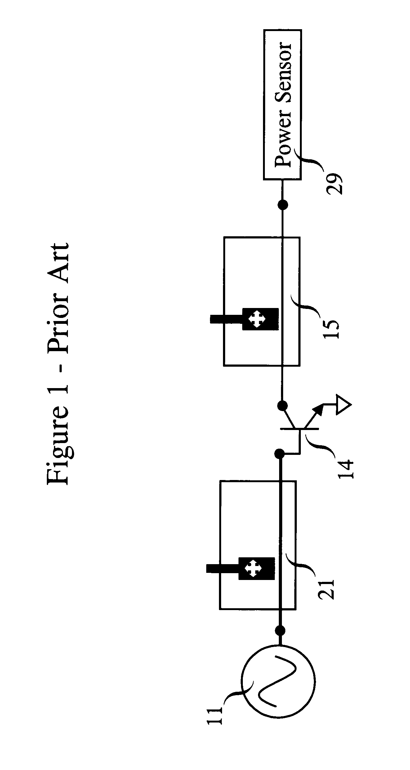
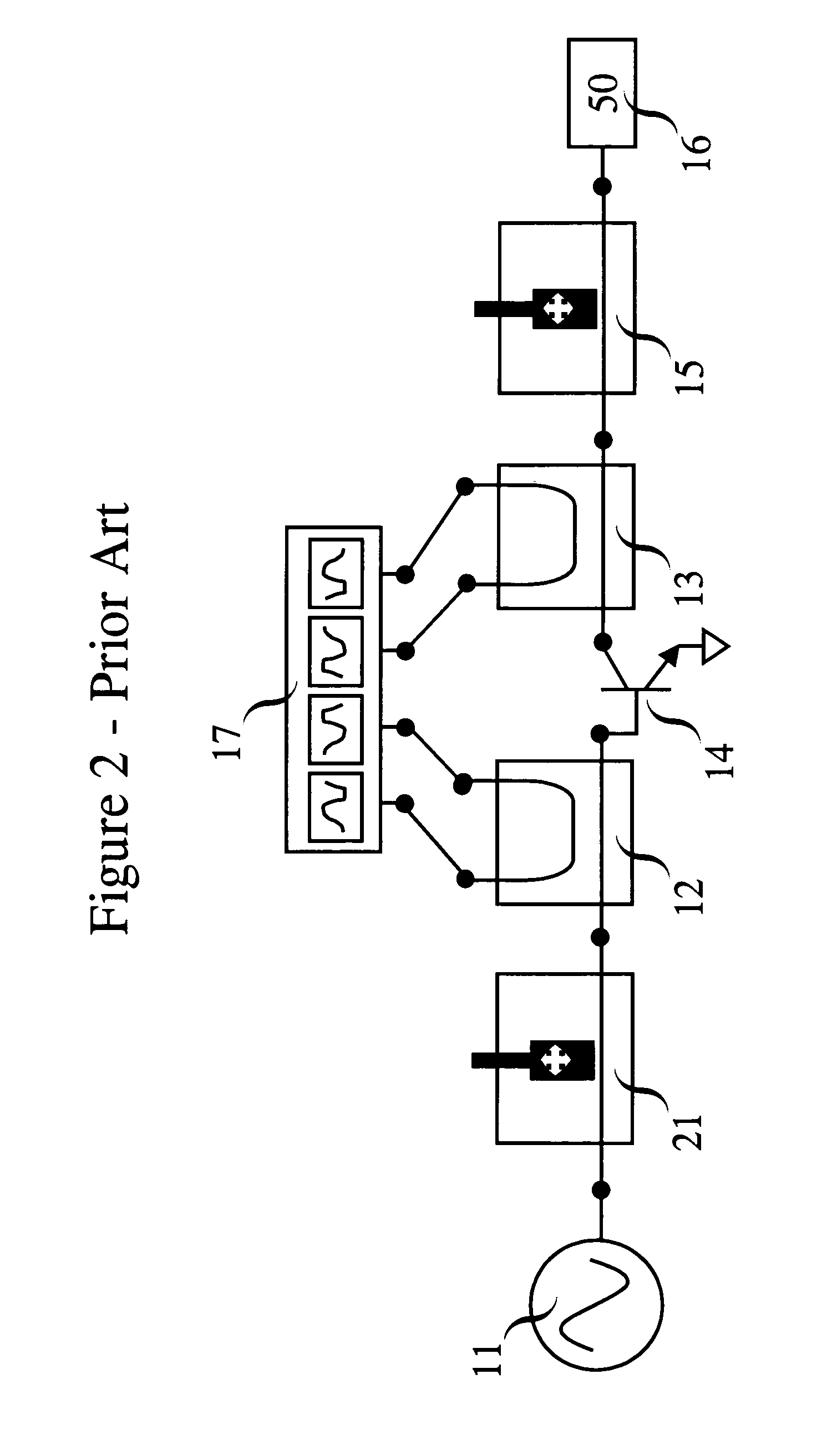
[0039]First we will describe the hardware components of a real-time load-pull setup as depicted in FIG. 2. The signal source 11 is connected to the input tuner 21. The input tuner 21 is connected to the input wave sensing structure 12. The othe...


PUM


Abstract

A calibration procedure for a real-time load-pull system whereby the signal passes through at least one of the tuners of said real-time load-pull system. A calibration standard is connected to the test ports and an electromagnetic wave signal passes through one of the tuners before passing through the wave sensing structure. After having passed the wave sensing structure the electromagnetic wave signal interacts with the calibration element. This results in a reflected and eventually a transmitted electromagnetic wave signal that pass through the wave sensing structures of the system. The sensed electromagnetic wave signals are measured by means of a receiver. The procedure is repeated with different calibration standards. Then a line element is connected to the test ports and, one after the other, a set of calibration standards, a power meter and a harmonic phase reference generator are connected to the output tuner, each time sending a signal and measuring the wave signals. The measured data is used to calculate the error coefficients of the real-time load-pull system.

Description

CROSS-REFERENCE TO RELATED APPLICATIONS [0001]Not ApplicableFEDERALLY SPONSORED RESEARCH [0002]Not ApplicableSEQUENCE LISTING OR PROGRAM [0003]Not ApplicableBACKGROUND OF THE INVENTION[0004]1. Field of Invention[0005]The present invention relates to the measurement of incident and reflected waveforms for microwave and radio-frequency (RF) devices-under-test (DUTs) under realistic large signal operating conditions.[0006]2. Description of the Related Art[0007]Modern wireless telecommunication systems use complex signals at high carrier frequencies, with frequencies typically in the GHz range. These signals are generated by electrical circuitry, like e.g. modulators and mixers that can typically only handle low power levels in the milliwatt range. The generated low power signals are amplified to a higher power level before being sent to the antenna. At the antenna power levels range from about 1 Watt for a cellular phone to about 100 Watt for a base station. The amplification of the si...

Claims


Application Information

Patent Timeline
Patent Type & Authority Applications(United States)
IPC IPC(8): G01R27/06
CPCG01R35/005G01R27/28
Inventor VERSPECHT, JANDE GROOTE, FABIEN
Owner VERSPECHT JAN
Why Eureka
Try Eureka