System and method of a reservoir monitoring system

a monitoring system and reservoir technology, applied in the field of hydrocarbon reservoir monitoring, can solve the problems of significant challenges for marine-based permanent reservoir monitoring

Active Publication Date: 2014-02-13
GEOSPACE TECH
View PDF18 Cites 45 Cited by
  • Summary
  • Abstract
  • Description
  • Claims
  • Application Information

AI Technical Summary

Problems solved by technology

Marine-based permanent reservoir monitoring faces significant challenges that are not faced by land-based permanent monitoring systems.

Method used


Image

  • System and method of a reservoir monitoring system
  • System and method of a reservoir monitoring system
  • System and method of a reservoir monitoring system

Examples


Embodiment Construction

[0026]The following discussion is directed to various embodiments of the invention. Although one or more of these embodiments may be preferred, the embodiments disclosed should not be interpreted, or otherwise used, as limiting the scope of the disclosure or the claims. In addition, one skilled in the art will understand that the following description has broad application, and the discussion of any embodiment is meant only to be exemplary of that embodiment, and not intended to intimate that the scope of the disclosure or the claims is limited to that embodiment.

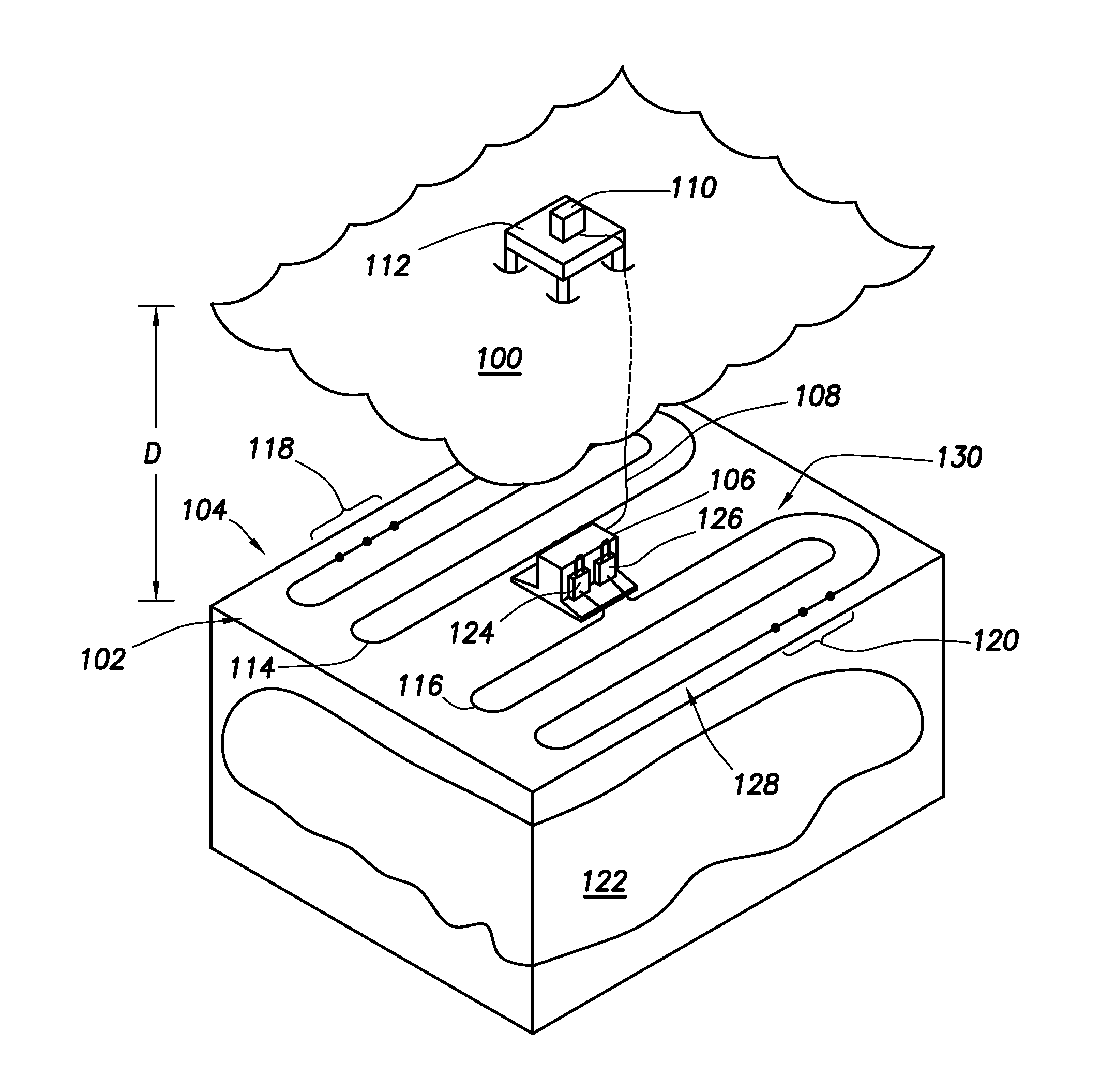
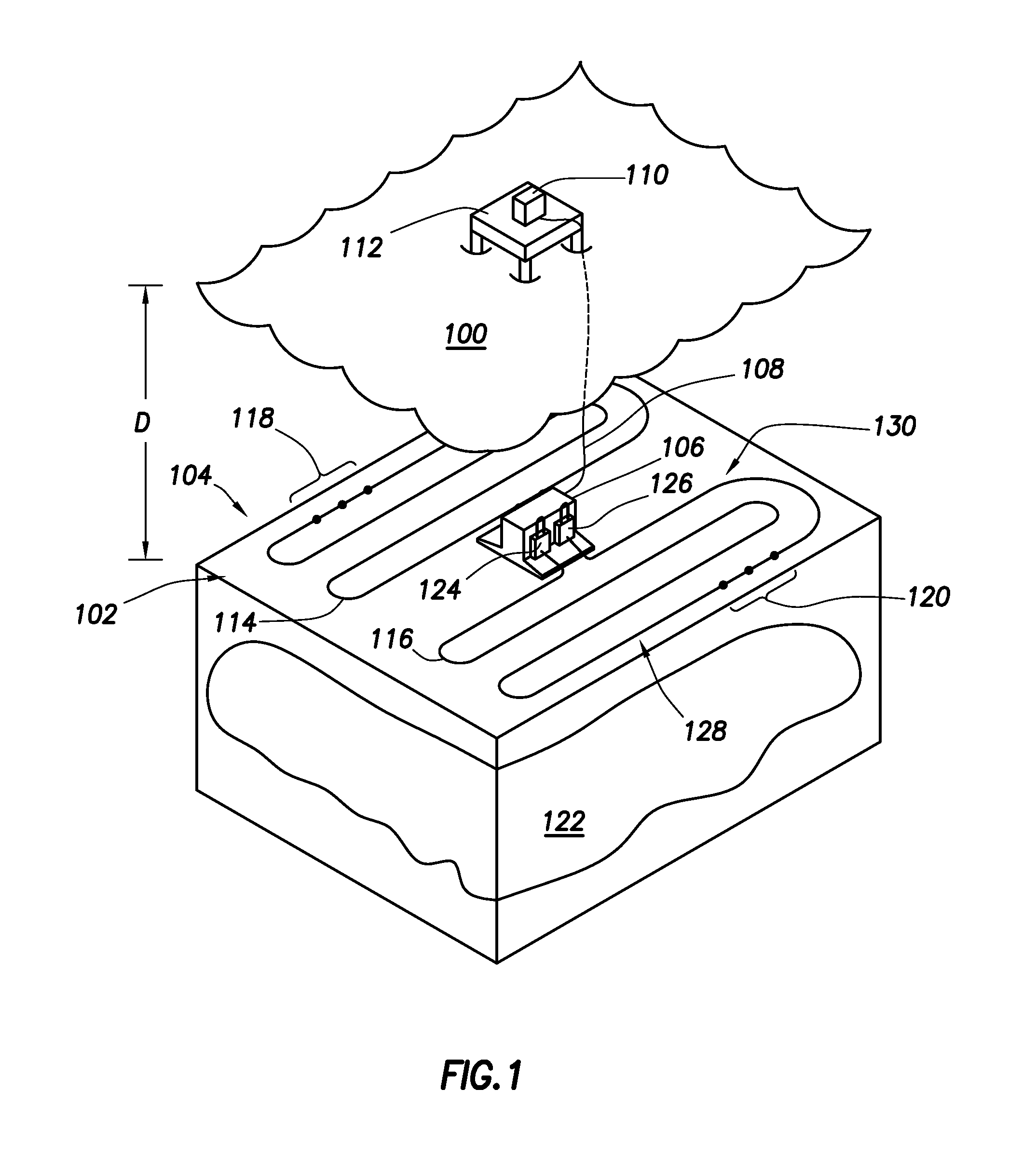
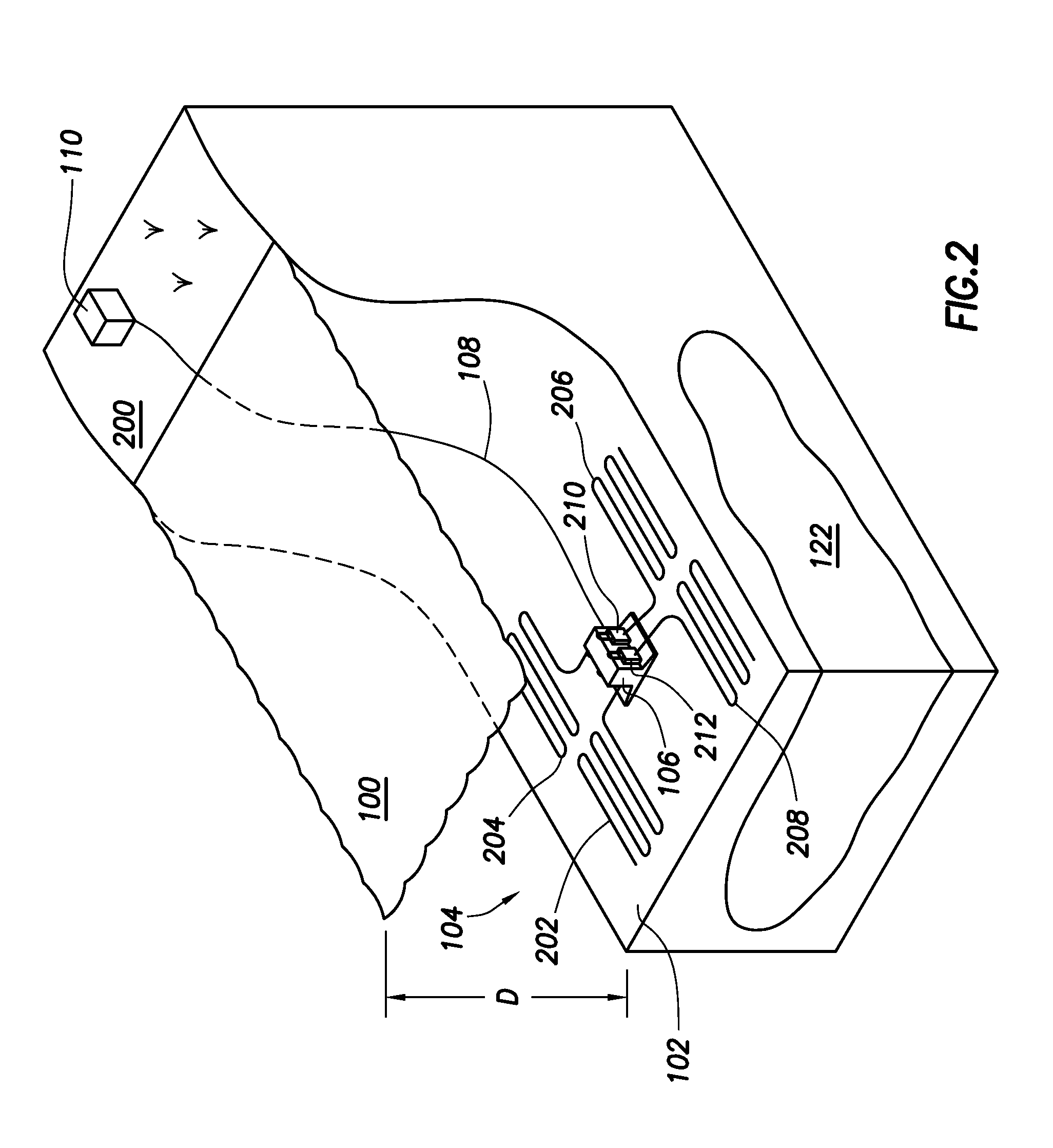
[0027]The various example systems and methods are directed to permanent hydrocarbon reservoir monitoring systems used in marine environments (e.g., in the range of 1000 meters of water depth). Permanent in this context indicating that the example systems can be used in reservoir monitoring where the various devices for monitoring are left on the sea floor indefinitely; however, the example systems can be used in any reservo...


PUM


Abstract

Reservoir monitoring system. At least some of the illustrative embodiments are methods comprising installing a hydrocarbon reservoir monitoring system in a marine environment. The installing may be by: placing a base unit at the sea floor, the base unit communicatively coupled to a computer system at the surface, the communicative coupling by way of an umbilical cable; mechanically coupling a first termination module to the base unit, the termination module coupled to a first sensor cable; and communicatively coupling the first sensor cable to the umbilical cable.

Description

BACKGROUND[0001]Permanent hydrocarbon reservoir monitoring is a technique where multiple three-dimensional seismic “pictures” of the state of a hydrocarbon reservoir are taken such that a geologist or reservoir engineer may plan the location of additional boreholes for increasing the efficiency of the hydrocarbon extraction and / or may assess the efficiency of the current extraction techniques over time. In some cases, taking multiple seismic pictures of a hydrocarbon reservoir may be referred to as four-dimensional (4D) seismic.[0002]Marine-based permanent reservoir monitoring faces significant challenges that are not faced by land-based permanent monitoring systems. This is particularly true of ocean bottom installations as water depths extend into the 1000 meter range and beyond.BRIEF DESCRIPTION OF THE DRAWINGS[0003]For a detailed description of exemplary embodiments, reference will now be made to the accompanying drawings in which:[0004]FIG. 1 shows a perspective cut-away view o...

Claims


Application Information

Patent Timeline
Patent Type & Authority Applications(United States)
IPC IPC(8): G01V1/28
CPCG01V1/22G01V1/3852G01V2210/6122G01V1/201G01V1/226E21B41/0007E21B47/001
Inventor SMITH, AARON B.METZBOWER, D. RICHARD
Owner GEOSPACE TECH
Why Eureka
Try Eureka