
Suturing device for treament of pelvic floor disorders

a technology for treating pelvic floor disorders and sutures, which is applied in the field of medical devices and procedures, can solve the problems of time-consuming suction of body tissues, misalignment between the needle and the needle catch slot, and the chance of needle and needle catch slot misalignmen

Active Publication Date: 2014-02-20
BOSTON SCI SCIMED INC
View PDF9 Cites 7 Cited by
  • Summary
  • Abstract
  • Description
  • Claims
  • Application Information

AI Technical Summary

Benefits of technology

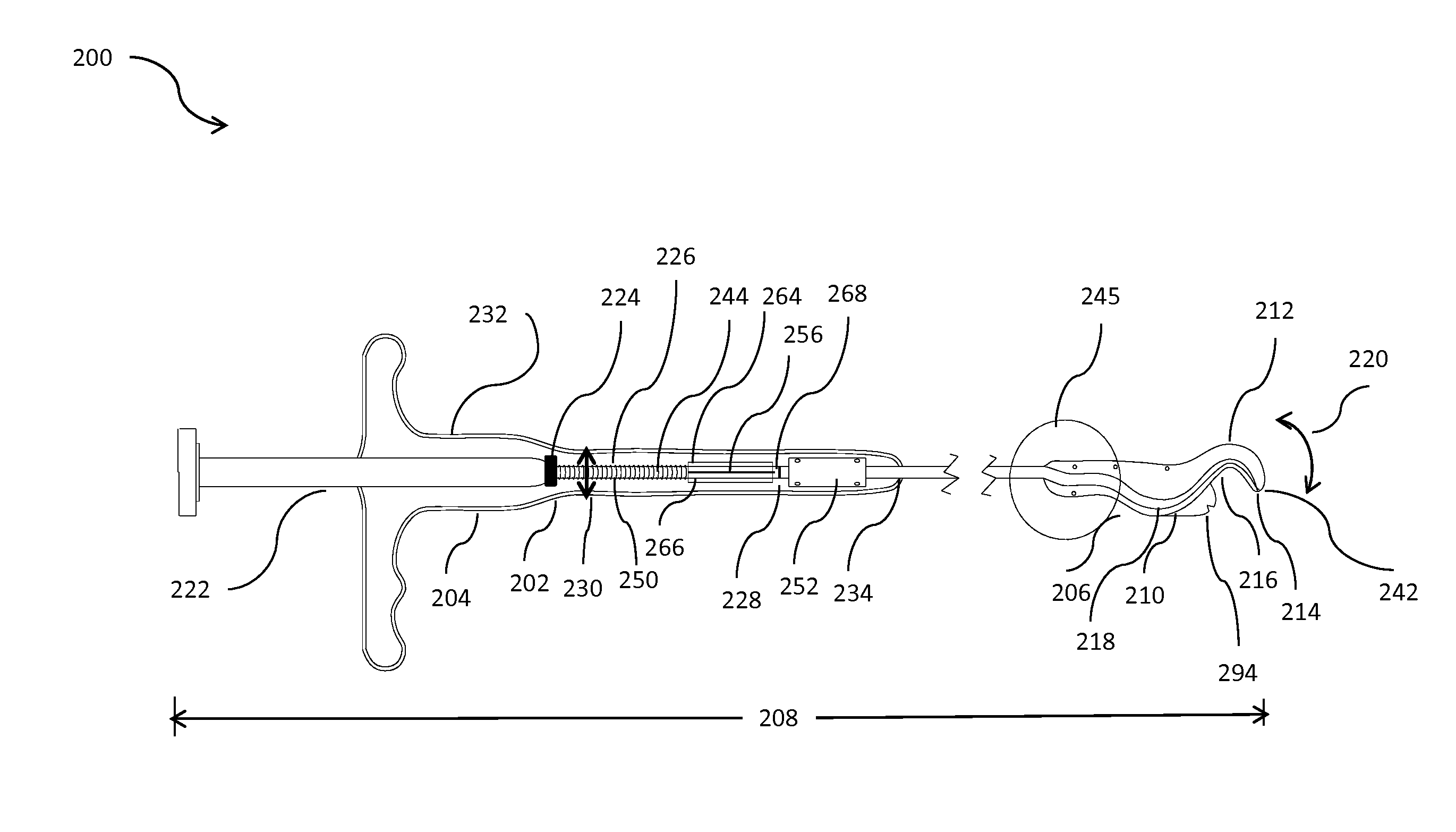
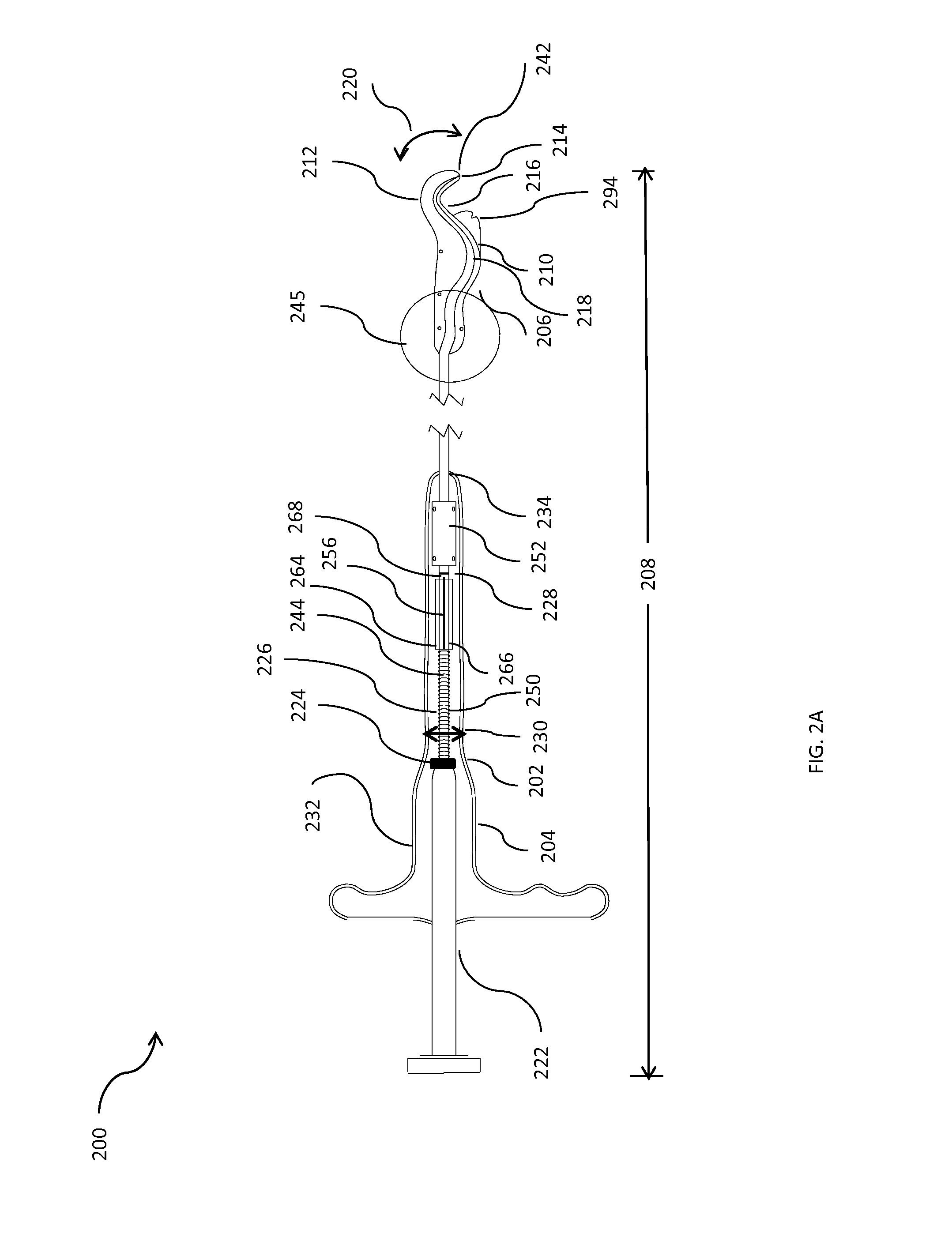
The present invention describes a suturing device with an elongate body member and a needle deployment mechanism. The device has a needle receiving portion with walls that converge towards an aperture to capture the needle. The needle is moved out of the device as a needle carrier deploys it from the distal portion of the elongate body member. The device can be used to suture bodily implants to bodily tissue using a suture loaded on the device. The technical effect of this invention is to provide a simple and effective tool for suturing bodily implants to bodily tissue.

Problems solved by technology

Suturing of body tissues may be time consuming and an important aspect of most surgical procedures.
In such devices, there is a chance of misalignment of the needle and the needle catch slot during the needle catch process when the needle is received in the needle catch slot.
However, often the needle hits a solid land area between the slots and this can cause a misalignment between the needle and the slots.
Further, the existing suturing devices have a blunt surface at the needle catch portion that may allow bodily tissues to get stuck inside the needle catch slot during the suturing.
This would again cause a device misalignment.
Also, the overall size of the current suturing devices causes the physician to perform more dissection of bodily tissue in order to access the required tissues.

Method used


Image

  • Suturing device for treament of pelvic floor disorders
  • Suturing device for treament of pelvic floor disorders
  • Suturing device for treament of pelvic floor disorders

Examples


Embodiment Construction

[0045]Detailed embodiments of the present invention are disclosed herein; however, it is to be understood that the disclosed embodiments are merely exemplary of the invention, which may be embodied in various forms. Therefore, specific structural and functional details disclosed herein are not to be interpreted as limiting, but merely as a basis for the claims and as a representative basis for teaching one skilled in the art to variously employ the present invention in virtually any appropriately detailed structure.

[0046]The terms “a” or “an,” as used herein, are defined as one or more than one. The term “another,” as used herein, is defined as at least a second or more. The terms “including” and / or “having”, as used herein, are defined as comprising (i.e., open transition).

[0047]The terms proximal and distal described in relation to various medical devices, apparatuses, and components (as discussed in the subsequent text of the present invention) are referred with a point of refere...


PUM


Abstract

The invention relates to a suturing device used to place sutures inside the human body during various medical procedures. The suturing device includes an elongate body member, a needle deployment mechanism and a needle receiving portion. The elongate body member has a distal portion that defines an opening. The needle deployment mechanism is disposed at least partially within the elongate body member for moving a needle out of the opening at the distal portion of the elongate body member into a tissue; and the needle receiving portion is provided at the distal portion of the elongate body member to capture the needle. The needle receiving portion has a non-planar surface with walls that are non-parallel with respect to a longitudinal direction of the needle receiving portion such that the walls converge to form an aperture formed in the needle receiving portion to receive the needle.

Description

CROSS-REFERENCE TO RELATED APPLICATION[0001]This application is a Nonprovisional of, and claims priority to, U.S. Patent Application No. 61 / 683,921, filed on Aug. 16, 2012, entitled “SUTURING DEVICE FOR TREATMENT OF PELVIC FLOOR DISORDERS”, which is incorporated by reference herein in its entirety.BACKGROUND[0002]1. Field of Invention[0003]The present invention generally relates to medical devices and procedures, particularly devices and methods for delivery and placement of medical implants into a patient's body.[0004]2. Description of the Related Art[0005]Suturing of body tissues may be time consuming and an important aspect of most surgical procedures. Many surgical procedures may be performed where it is necessary to make a large opening to expose the area, for instance, a bodily tissue of the human body, which requires a surgical repair. In various corrective surgeries or implant procedures, the bodily tissue must be returned to a normal anatomical position or placed in an impr...

Claims


Application Information

Patent Timeline
Patent Type & Authority Applications(United States)
IPC IPC(8): A61B17/04
CPCA61B17/0483A61B17/0469A61B2017/00805A61B2017/047A61B2017/0472A61B17/0625
Inventor TEAGUE, JAMES A.ZERFAS, JEFFREYLINGEMAN, JOHNGREEN, CHRISTOPHER
Owner BOSTON SCI SCIMED INC
Learn More