
Water stopper for sink

a technology for stopping plugs and sinks, which is applied in water installations, washstands, constructions, etc., can solve the problems of increasing manufacturing costs and inventory, and conventional water stopping heads, and achieves the effects of convenient and convenient assembling, convenient for customers to purchase, and reduced mold costs

Inactive Publication Date: 2014-02-27
WEI KANG IND
View PDF2 Cites 16 Cited by
  • Summary
  • Abstract
  • Description
  • Claims
  • Application Information

AI Technical Summary

Benefits of technology

The present invention has the advantage of allowing for the plug to be used in water stopper bases of different sizes as it can be resiliently deformed. This makes it easier and more convenient for customers to purchase and assemble. Additionally, the use of a plug that can be provided for most water stopper bases helps to reduce the number of plugs with different sizes, lowering costs and minimizing inventory.

Problems solved by technology

However, conventional water stopping heads may have problems such as (i) there are plenty of sinks and water stopper bases (60) on the market, the water discharging space (61) of different sizes cause a problem to the customer to choose the water stopping plug (73) of the same size.
The customer may have bought the water stopping plug (73) that does not match the water stopper bases (60), so he / she may have to return or change; (ii) the manufacturers may have to manufacture the water stopping plug (73) with several different sizes, and each size needs its corresponding mold, which would increase the manufacturing costs and inventory.

Method used


Image

  • Water stopper for sink
  • Water stopper for sink
  • Water stopper for sink

Examples


Embodiment Construction

[0016]The detailed description set forth below is intended as a description of the presently exemplary device provided in accordance with aspects of the present invention and is not intended to represent the only forms in which the present invention may be prepared or utilized. It is to be understood, rather, that the same or equivalent functions and components may be accomplished by different embodiments that are also intended to be encompassed within the spirit and scope of the invention.

[0017]Unless defined otherwise, all technical and scientific terms used herein have the same meaning as commonly understood to one of ordinary skill in the art to which this invention belongs. Although any methods, devices and materials similar or equivalent to those described can be used in the practice or testing of the invention, the exemplary methods, devices and materials are now described.

[0018]All publications mentioned are incorporated by reference for the purpose of describing and disclos...


PUM


Abstract

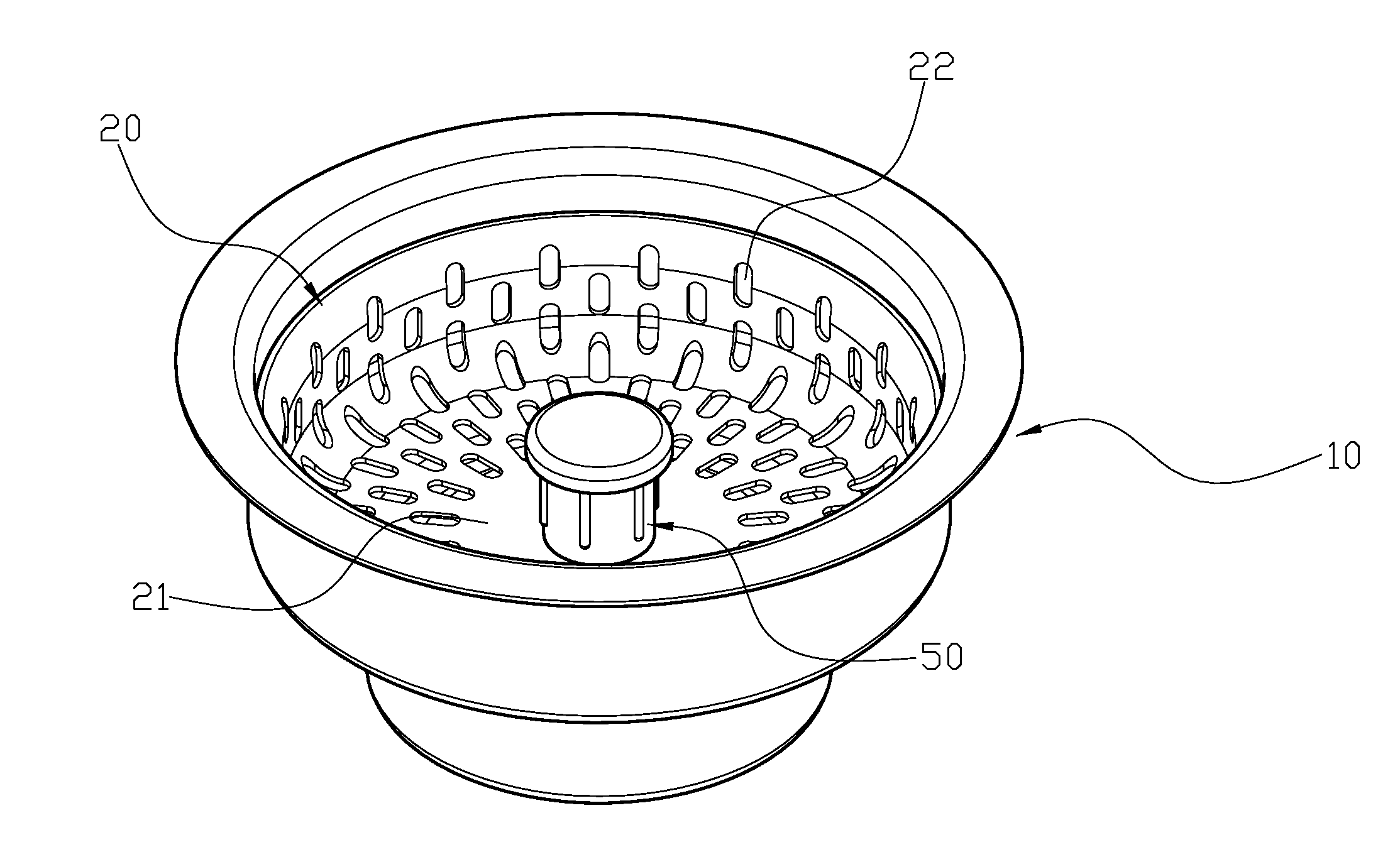
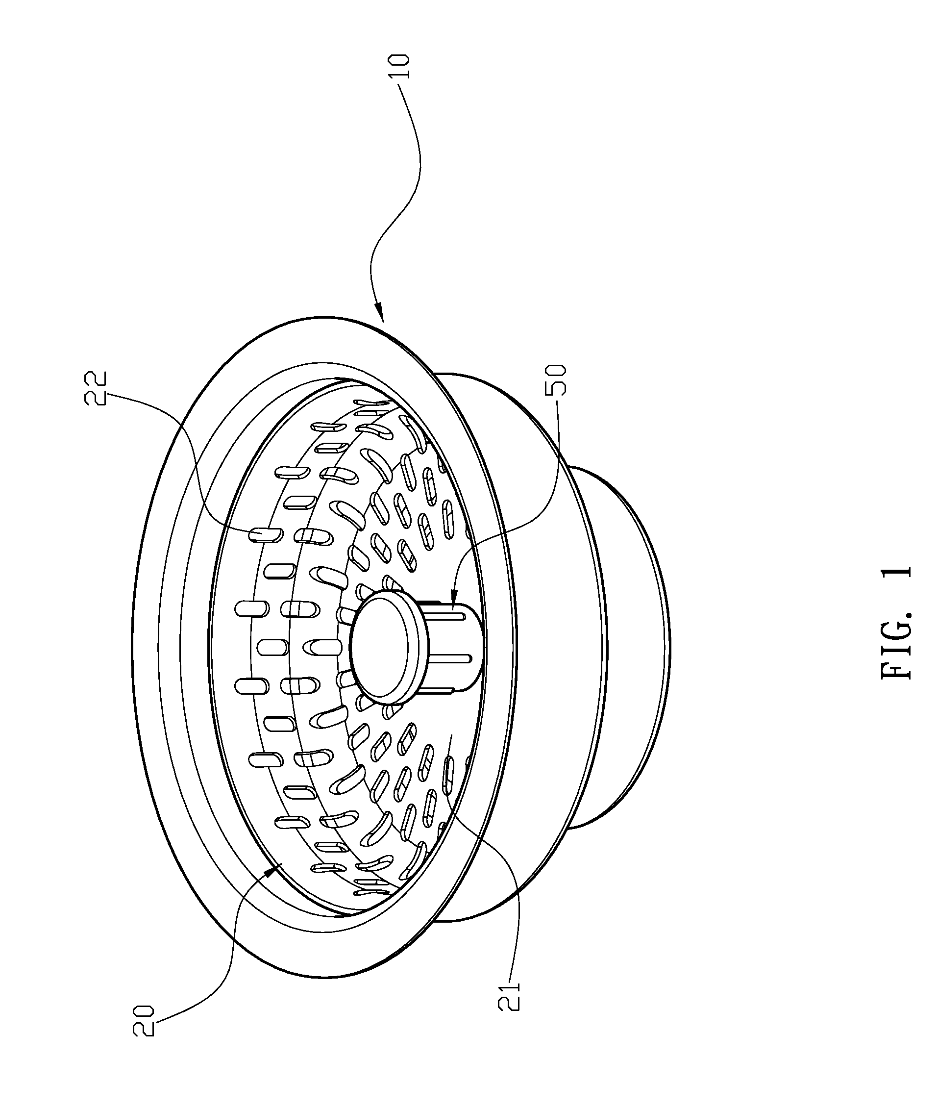
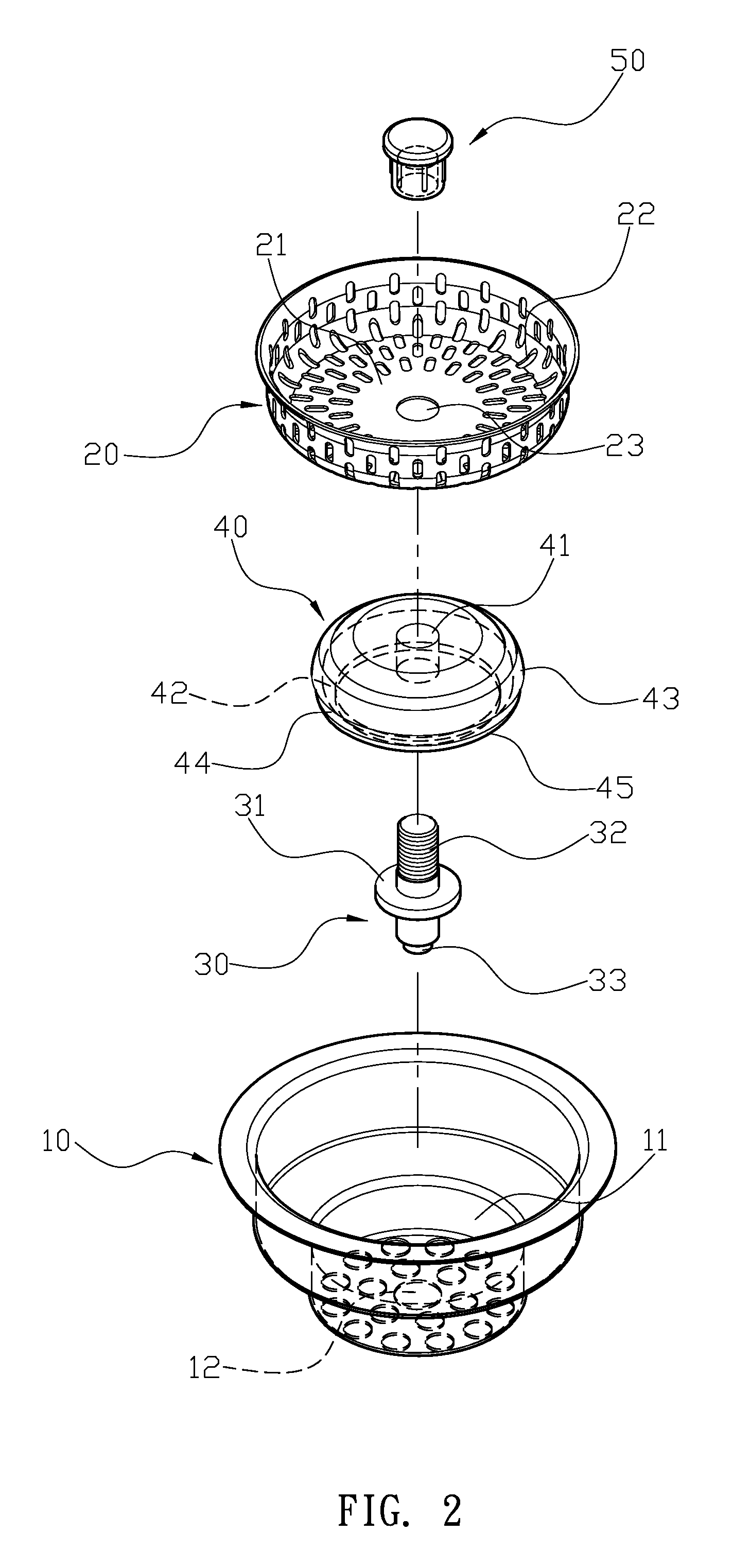
A water stopper for sink that is used in a water stopper base includes a water stopper body, a fixed rod, a plug and a pulling head. The plug is a rubber block having a through opening in the central portion thereof, and a trough is upwardly formed from the bottom surface of the plug. With the trough, the plug is able to sustain pressure from every side due to its resilient reformation. A circular protrusion is formed at an enlarged periphery of the plug, so that the lower portion of circular protrusion forms a guiding section, the rear end of which is tapered toward the trough to form a curved bottom edge.

Description

FIELD OF THE INVENTION[0001]The present invention relates to a water stopper plug for sink, and more particularly to a water stopper plug that can be used in a water stopper base of any sizes.BACKGROUND OF THE INVENTION[0002]Conventionally, a water stopping head (70) of a water stopping head base (60) can be shown in FIGS. 7 and 8, which includes a main body (71), a fixed rod (72), a water stopping plug (73) and a nut (74). A receiving space (711) is recessedly formed in the main body (71), and a plurality of water filtering holes (712) are in the receiving space (711). A through hole (713) is formed at the bottom surface of the receiving space (711), and the through hole (713) can be used to secure the fixed rod (72). The fixed rod (72) is enlarged in the middle section to form a stopping edge (721), and a locking pole (722) extends from an upper portion of the fixed rod (72) to pass through a central through hole (731) of the water stopping plug (73) and into the through hole (713...

Claims


Application Information

Patent Timeline
IPC IPC(8): A47K1/14
CPCE03C1/262
Inventor LEE, TSUNG-LIEH
Owner WEI KANG IND
Learn More