Cooling device and image forming apparatus
- Summary
- Abstract
- Description
- Claims
- Application Information
AI Technical Summary
Benefits of technology
Problems solved by technology
Method used
Image
Examples
configuration example 1
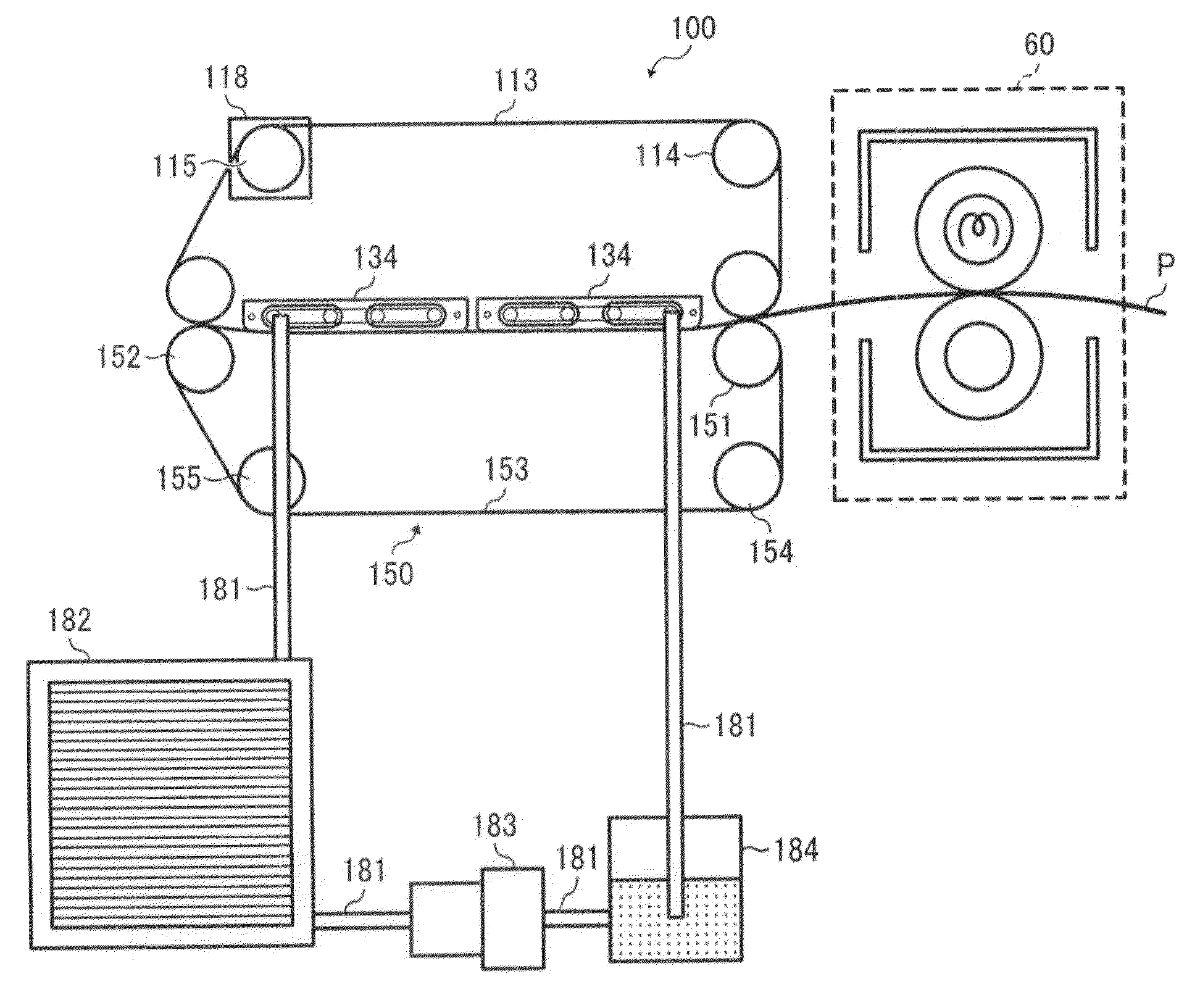
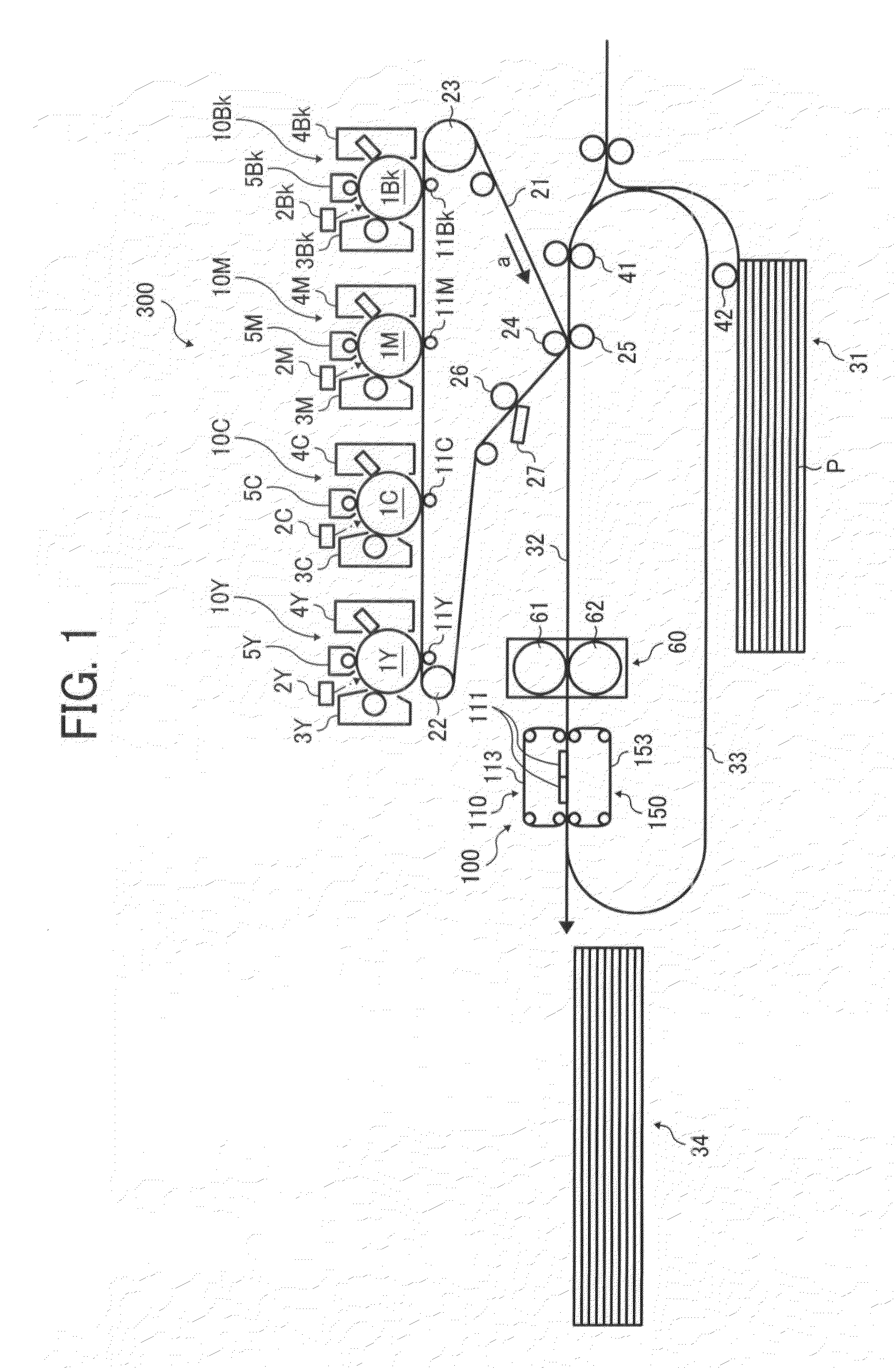
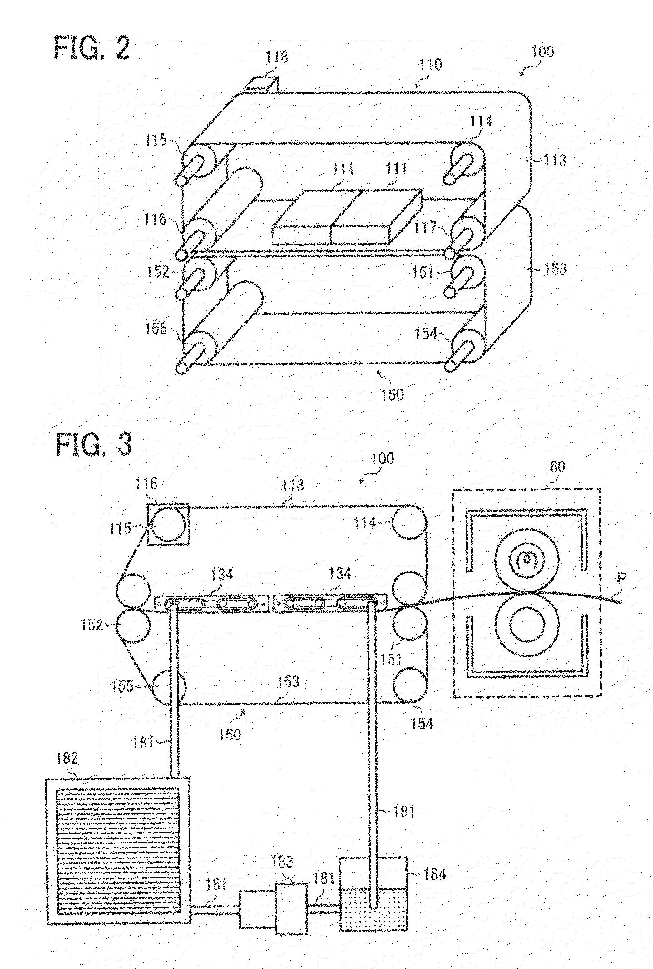
[0080]According to configuration example 1, the cooling member 111 is removable from the cooling device main body. FIG. 4 shows a cooling device equipped with two cooling members 111 for users to print a large number of thick paper sheets having a large thermal capacity and which is difficult to cool. Meanwhile, FIG. 5 shows a cooling device equipped with the cooling member 111 for users to use only thin paper or plane paper having a smaller thermal capacity and which is easy to cool. Thus, it is possible to prevent higher costs by only providing sufficient equipment for the desired performance.
[0081]In addition, if the print volume or the type of paper has changed, a user can simply add another cooling member 111.
[0082]FIG. 4 and FIG. 5 show a cooling device that accommodates a maximum of two cooling members 111, but the maximum number of cooling members 111 may be arbitrary.
[0083]In order to generate a uniform contact pressure between the cooling surface of the cooling member 111 ...
configuration example 2
[0091]According to configuration example 2, a plurality of the auxiliary rollers 8 for adjusting tension of the upper transport belt 11 are installed at a position of the cooling surface where adjacent the cooling members 111 on the inside of the cooling device 100, as shown in FIG. 12. The auxiliary rollers 8 make the tension of the upper transport belt 113 nearly the same as the tension with the maximum of two cooling members 111.
[0092]When the auxiliary roller 8 is installed on the upper transport belt 113 as shown in FIG. 12, there is less abrasion than when the auxiliary member 7, as shown in FIG. 9 is installed. Therefore, the auxiliary member 8 prevents the upper transport belt 113 from sliding.
configuration example 3
[0093]FIGS. 13 and 14 show another example of a tension adjustor of the upper transport belt 113 according to a change in the number of cooling members 111 included.
[0094]As another means for adjusting the slack of the upper transport belt 113, the position of at least one of the extending rollers that extend the upper transport belt 113 and the lower transport belt 153 is changeable, in accordance with the number of the cooling members ill.
[0095]For example, as shown in FIG. 13, changing the position of the extending rollers 119 and 156 adjusts the tension of the upper transport belt 113 and the lower transport belt 153. Also as shown in FIG. 14, a plurality of pressure rollers 157 assist in adjusting the cooling members 111, the upper transport belt 113, the lower transport belt 153, and the sheet P when passing between the upper transport belt 113 and the lower transport belt 153. In addition, the plurality of pressure rollers 157 may adjust the tension of the upper transport bel...
PUM
 Abstract
Description
Claims
Application Information
 - R&D
- Intellectual Property
- Life Sciences
- Materials
- Tech Scout
- Unparalleled Data Quality
- Higher Quality Content
- 60% Fewer Hallucinations
Browse by: Latest US Patents, China's latest patents, Technical Efficacy Thesaurus, Application Domain, Technology Topic, Popular Technical Reports.
© 2025 PatSnap. All rights reserved.Legal|Privacy policy|Modern Slavery Act Transparency Statement|Sitemap|About US| Contact US: help@patsnap.com


