
Standoff device and method of installation of harness

a technology of standoff device and harness, which is applied in the direction of supporting insulators, pipe supports, electrical equipment, etc., can solve the problem of inefficient manpower and material use of wire harnesses for installation

Active Publication Date: 2014-03-06
BOMBARDIER CORP
View PDF9 Cites 17 Cited by
  • Summary
  • Abstract
  • Description
  • Claims
  • Application Information

AI Technical Summary

Benefits of technology

The present patent aims to provide a standoff device that addresses issues associated with prior art devices. The standoff device includes a fixation portion, a spacing portion, and a connector portion. The connector portion has a retaining clip that resiliently deforms to hold a wire harness connector component in place. The device also includes an elastomeric absorber and an indexation formation to secure the wire harness connector component in a specific orientation. The cable support interfacing the wire harness to the standoff device has an elongated body with one or more abutment surfaces that engage with complementary abutment surfaces on the standoff device to prevent the wire harness connector component from moving back onto the fixation portion. The cable support also includes a through bore and indexation formations to securely hold the wire harness connector component in place. The method of connecting and disconnecting a wire harness to a structure with a standoff device involves threading an opening of the wire harness connector component onto the retaining clip of the standoff device. The technical effects of the invention include improved stability, reliability, and flexibility in connecting wire harness to a structure with a standoff device.

Problems solved by technology

However, the installation of such wire harnesses is inefficient in terms of manpower.
For instance, standoffs are commonly used to connect wire harnesses to structures, but these standoffs often require bolting / screwing manipulations for the wire harnesses to be fixed to the structure.

Method used


Image

  • Standoff device and method of installation of harness
  • Standoff device and method of installation of harness
  • Standoff device and method of installation of harness

Examples


Embodiment Construction

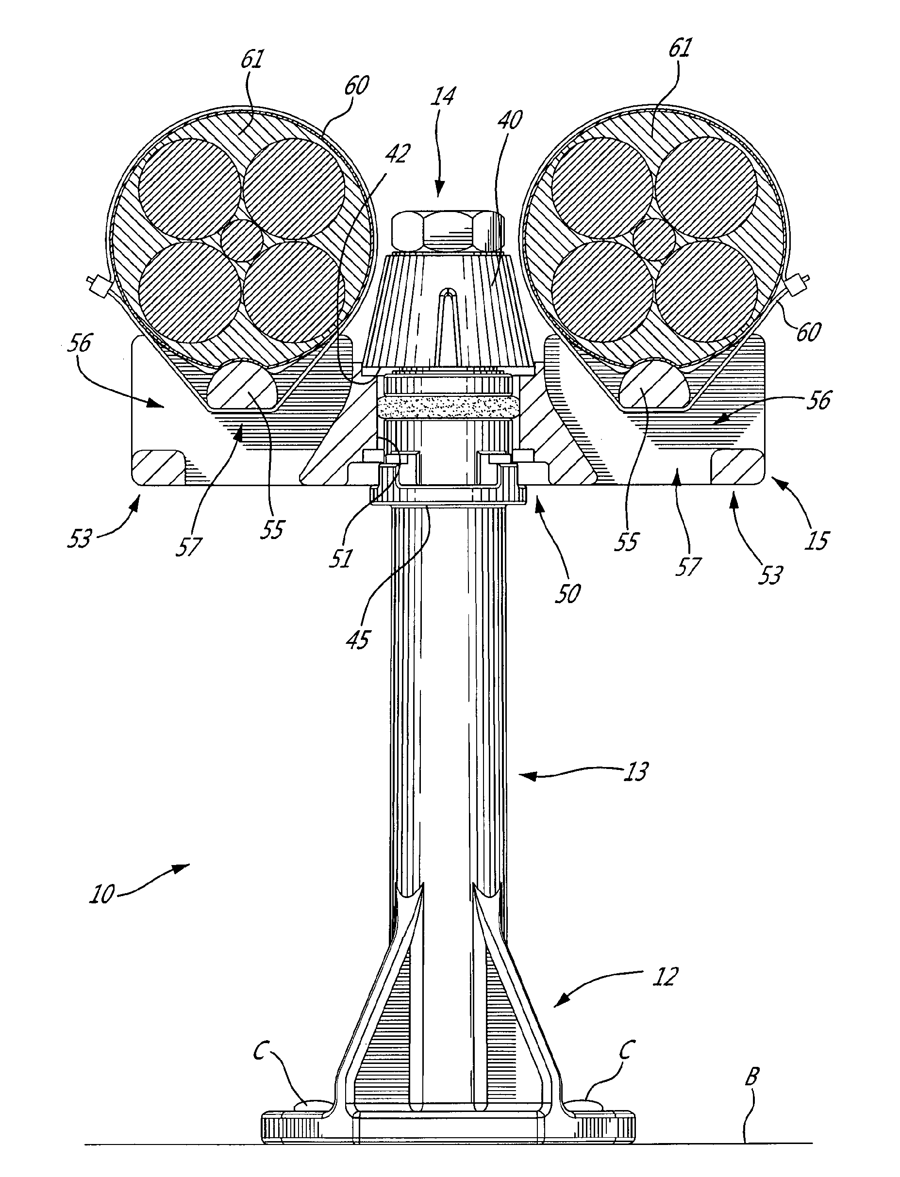
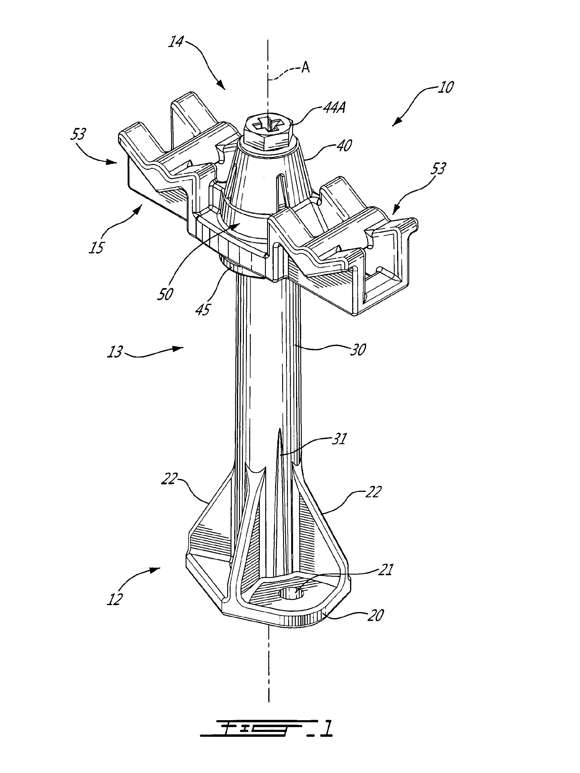
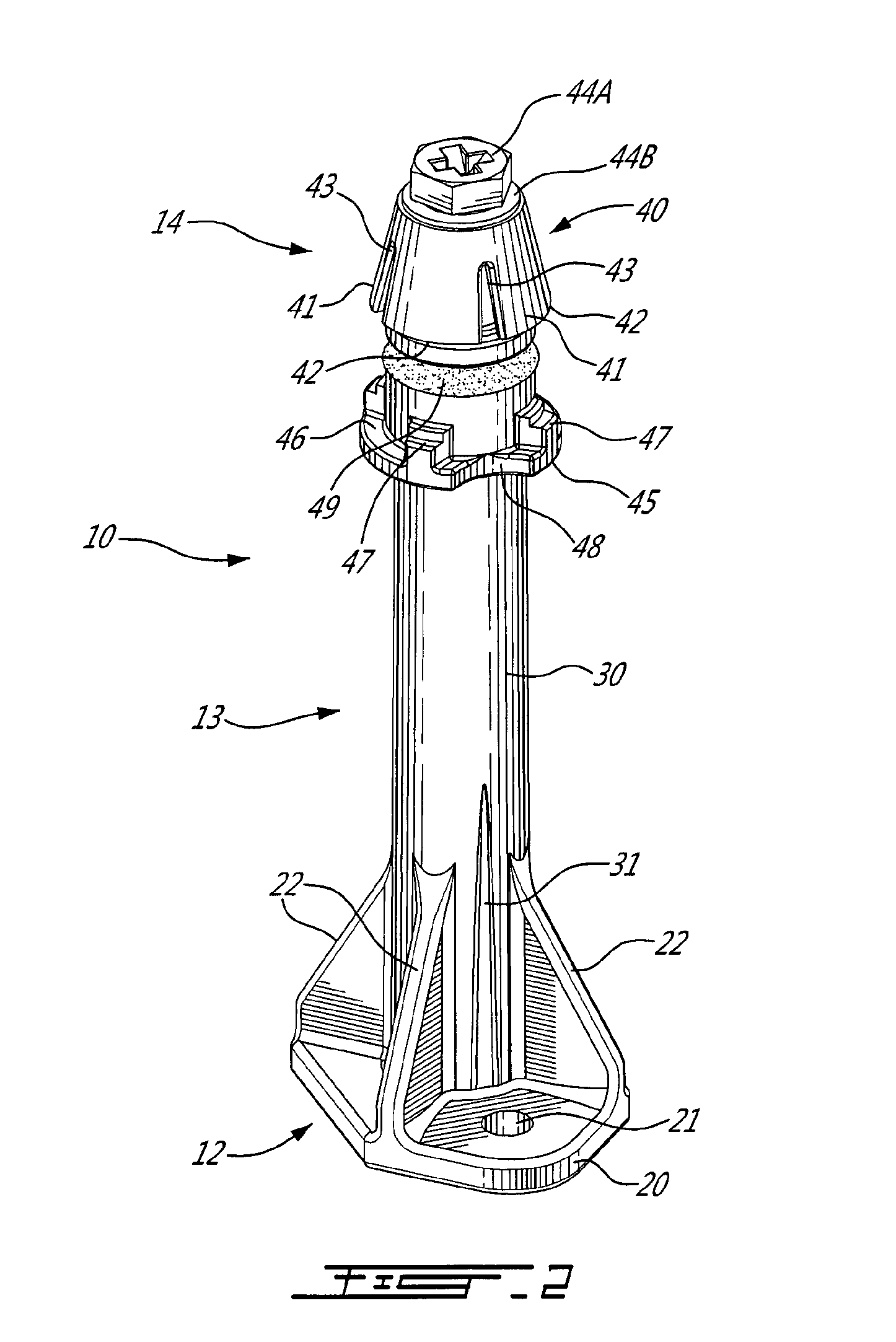
[0061]Referring to the drawings, and more particularly to FIGS. 1-3, a standoff device is generally shown at 10. The standoff device, occasionally referred to hereinafter as “device 10” for simplicity purposes, is also known as a standoff, harness connector, connection post, among other possible names. The standoff device 10 is used to connect a wire harness or wire harnesses to a structure, while physically spacing the wire harness or harnesses apart from the structure (i.e., standing off the wire harness from the structure).

[0062]The device 10 has a fixation portion 12, a spacing portion 13, and a connector portion 14. A cable support 15 is releasably secured to the connector portion 14 of the device 10.

[0063]The fixation portion 12 is the interface between the device 10 and a structure.

[0064]The spacing portion 13 projects from the fixation portion 12 and distances the connector portion 14 from the structure, whereby the wire harness is held at a stand-off distance from the struc...


PUM


Abstract

A device connects a wire harness to a structure. A fixation portion of the device is secured to the structure. A spacing portion is connected to the fixation portion and to a connector portion. A retaining clip on the connector portion deforms when a wire harness connector component moves axially toward the fixation portion. The clip opposes an abutment edge against the component into engagement position when the component is past the clip to prevent it from moving back onto the clip. An abutment surface contacts another portion of the component in engagement position to prevent further axial movement of the component toward the fixation portion. The component is held captive between the edge and the abutment surface. Also provided are a cable support for connecting the wire harness to the device, a method for connecting and disconnecting the wire harness to a structure with the device, and an aircraft.

Description

FIELD OF THE APPLICATION[0001]The present application relates to standoff devices used to connect wire harnesses to structures, for instance in aircraft.BACKGROUND OF THE ART[0002]Sophisticated vehicles such as aircraft feature wire harnesses relating the multiple wires used for the operation of aircraft systems. However, the installation of such wire harnesses is inefficient in terms of manpower. For instance, standoffs are commonly used to connect wire harnesses to structures, but these standoffs often require bolting / screwing manipulations for the wire harnesses to be fixed to the structure. It would be desirable to reduce the amount of manpower required to secure wire harnesses to structures.SUMMARY OF THE APPLICATION[0003]It is therefore an aim of the present disclosure to provide a standoff device that addresses at least some issues associated with the prior art.[0004]It is a further aim of the present disclosure to provide a cable support interfacing the wire harness to the s...

Claims


Application Information

Patent Timeline
IPC IPC(8): H01B17/16
CPCH01B17/16H02G3/30F16L3/237H01B17/14H02G3/32F16L3/221
Inventor DESHAIES, MARTINLANDRY, PIERREPAUZE, MARTINWOOD, KEITH ANTHONY
Owner BOMBARDIER CORP
Learn More