
Apparatus and method for driving light source in backlight unit

a backlight unit and light source technology, applied in the field of backlight units, can solve the problems of complicated design of the light source driver, and increasing the size of the light source driver, and achieves low reference clock and small operation logic.

Active Publication Date: 2014-03-06
LG DISPLAY CO LTD
View PDF2 Cites 2 Cited by
  • Summary
  • Abstract
  • Description
  • Claims
  • Application Information

AI Technical Summary

Benefits of technology

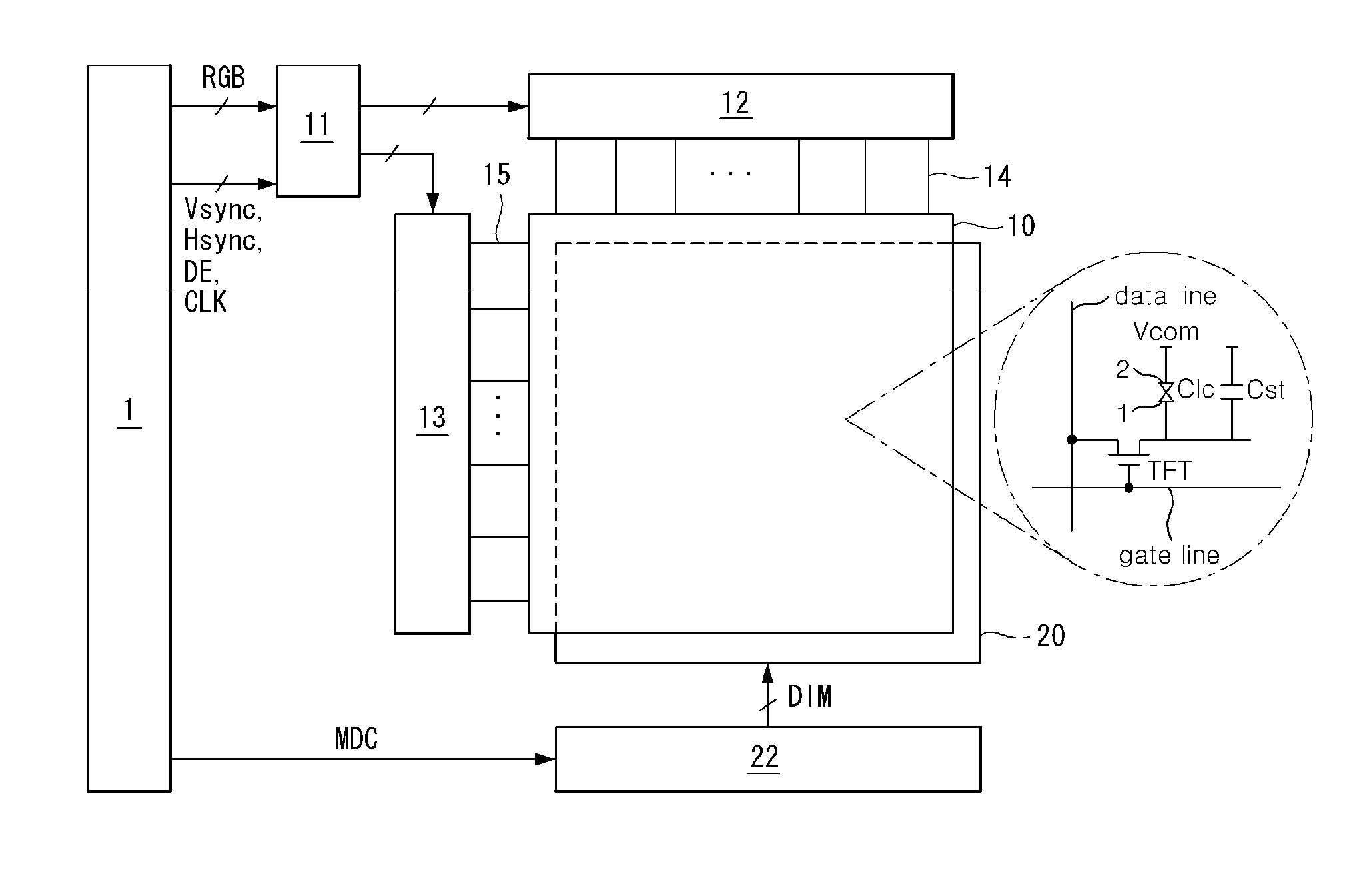
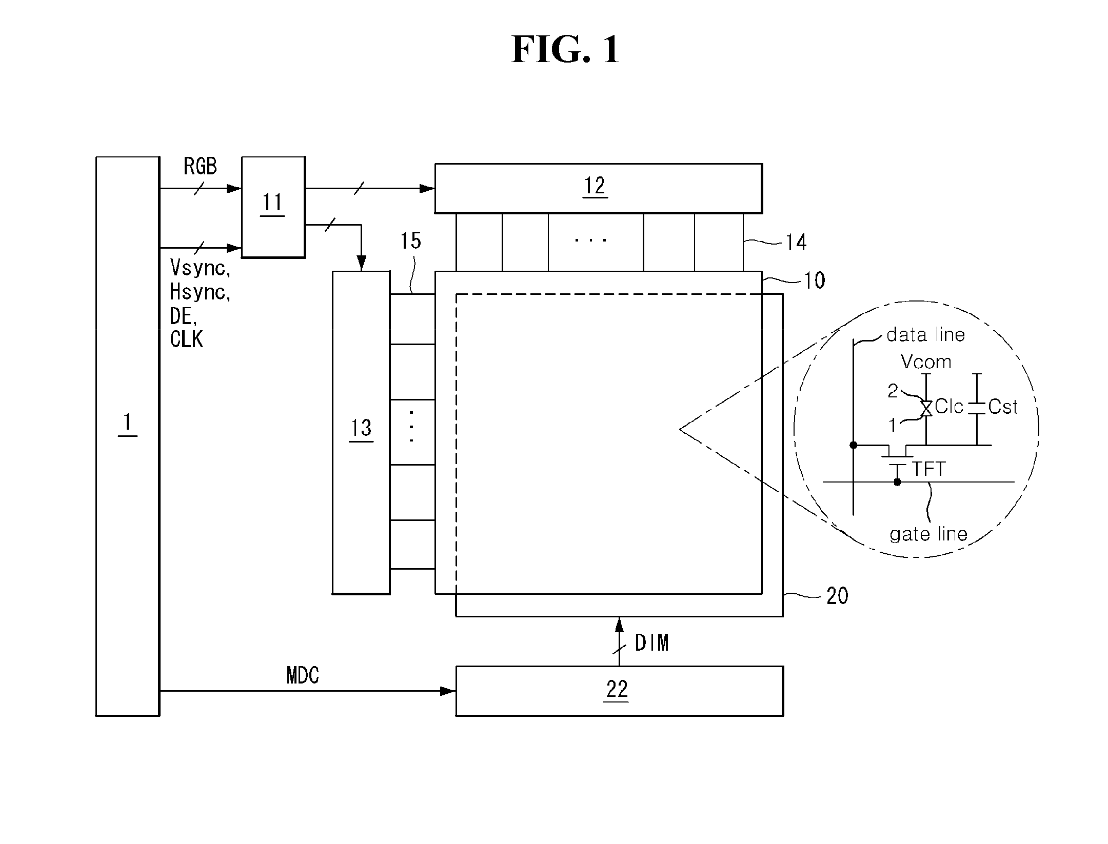
The present invention provides an apparatus and method for driving a light source in a backlight unit that can implement idle mode dimming with low operation logic and a low reference clock. The apparatus includes light sources and a light source driver that uses PWM control and PWM count control in a time-series manner to adjust the brightness of the light sources. This results in a first dimming value during a first period and a second dimming value that is lower than the first dimming value during a second period. The technical effect of this invention is that it allows for low dimming in an idle mode while using less operational logic and reference clock, which can save power and reduce the size of the apparatus.

Problems solved by technology

However, in the related art light source driving device using PWM, an operation logic of minimum 13 bits or greater is required to calculate an output dimming value of 0.02% or smaller implemented in an idle mode and designing a light source driver is complicated.
In addition, in order to implement an output dimming value as low as about 0.02% in an output dimming frequency band as fast as about 20 kHz, a reference clock of 100 MHz or higher is required, and in this case, since the related art light source driver should be designed to process operation data according to the reference clock, a configuration thereof is inevitably complicated.
As the light source driver is designed to be complicated, a size of the light source driver is increased and unit cost of a product is increased accordingly.

Method used


Image

  • Apparatus and method for driving light source in backlight unit
  • Apparatus and method for driving light source in backlight unit
  • Apparatus and method for driving light source in backlight unit

Examples


first embodiment

of Operation of Light Source Driver 22

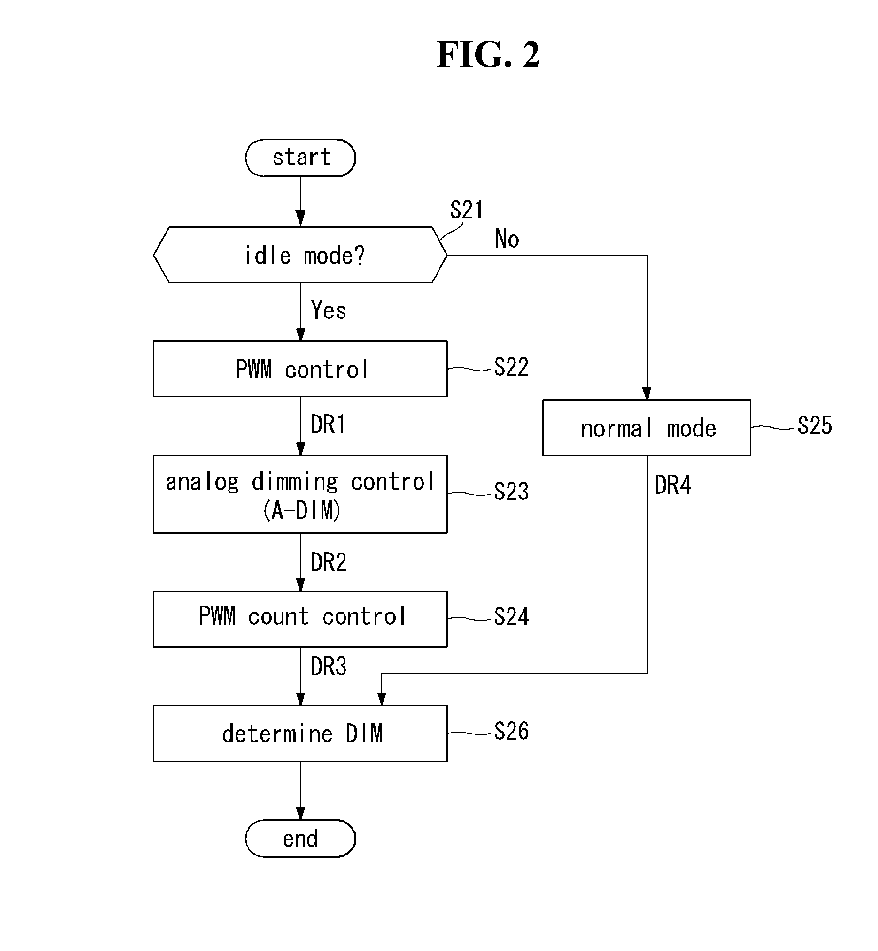
[0037]FIG. 2 is a flow chart illustrating an example of an operation of the light source driver 22 for implementing low dimming. FIG. 3 is a view illustrating a concept of controlling an output dimming value according to the operation of FIG. 2.

[0038]The light source driver 22 according to a first embodiment further performs analog dimming control between PWM control and PWM count control which are sequentially performed. In order to implement low dimming, the light source driver 22 lowers the dimming value DIM of the output dimming signal to a first dimming value during a PWM control period, lowers the dimming value DIM to a second dimming value during an analog dimming control period, and subsequently lowers the dimming value DIM to a third dimming value during a PWM count control period, thus implementing the output dimming value DIM of 0.02%. A size of a calculation logic and a speed of a reference clock are dependently only upon the first d...

second embodiment

of Operation of Light Source Driver 22

[0043]FIG. 4 is a flow chart illustrating another example of an operation of the light source driver 22 for implementing low dimming. FIG. 5 is a view illustrating a concept of controlling an output dimming value DIM according to the operation of FIG. 4.

[0044]The light source driver 22 according to the second embodiment of the present invention further performs analog dimming control before the PWM control and the PWM count control which are sequentially performed. Namely, the light source driver 22 further performs analog dimming control before the PWM control. In order to implement low dimming, the light source driver 22 lowers the dimming value DIM of the output dimming signal to a first dimming value during the analog dimming control period, lowers the dimming value DIM to a second dimming value during the PWM control period, and subsequently lowers the dimming value DIM to a third dimming value during the PWM count control period, thus impl...

third embodiment

of Operation of Light Source Driver 22

[0050]FIG. 6 is a flow chart illustrating still another example of an operation of the light source driver 22 for implementing low dimming. FIG. 7 is a view illustrating a concept of controlling an output dimming value according to the operation of FIG. 6.

[0051]The light source driver 22 according to the third embodiment of the present invention further performs analog dimming control after the PWM control and the PWM count control which are sequentially performed. Namely, the light source driver 22 further performs analog dimming control after the PWM count control. In order to implement low dimming, the light source driver 22 lowers the dimming value DIM of the output dimming signal to a first dimming value during a PWM control period, lowers the dimming value DIM to a second dimming value during the PWM count control period, and subsequently lowers the dimming value DIM to a third dimming value during the analog dimming control period, thus i...


PUM


Abstract

An apparatus for driving a light source of a backlight unit includes: light sources; and a light source driver operating in an idle mode according to an input dimming signal and reducing a dimming value of an output dimming signal for adjusting brightness of the light sources by stages by mixing PWM control and PWM count control in a time-series manner to thus implement low dimming in the idle mode, wherein the dimming value of the output dimming signal is lowered to a first dimming value through the PWM control during a first period and subsequently lowered to a second dimming value lower than the first dimming value through the PWM count control during a second period that follows the first period.

Description

[0001]This nonprovisional application claims priority under 35 U.S.C. §119(a) on Patent Application No. 10-2012-0096323 filed in Republic of Korea on Aug. 31, 2012, the entire contents of which are hereby incorporated by reference.BACKGROUND[0002]1. Field[0003]This document relates to a backlight unit irradiating light to a liquid crystal display (LCD) device, and more particularly, to an apparatus and method for driving a light source of a backlight unit.[0004]2. Related Art[0005]Applications of liquid crystal displays (LCDs) tend to extend gradually due to the characteristics that they are lighter and thinner and are driven with low power consumption. LCDs are used in portable computers such as notebook computers, office automation equipment, audio / video equipment, indoor / outdoor advertisement displays, and the like. Transmissive LCDs, making up the majority of LCDs, display an image by adjusting light incident from a backlight unit according to a data voltage by controlling a fie...

Claims


Application Information

Patent Timeline
Patent Type & Authority Applications(United States)
IPC IPC(8): H05B37/02
CPCH05B37/02G09G3/3406G09G2320/064G09G2330/022H05B45/10H05B47/165H05B45/37H05B47/10
Inventor AHN, YOUNGHUNKIM, JONGDAEKIM, SANGGYUYOON, BYUNGGIPARK, MINWOO
Owner LG DISPLAY CO LTD
Learn More