Touch display screen used for adjusting and determining the reticle of an electronic firearm sight

a technology of electronic firearm sight and display screen, which is applied in the direction of sighting devices, weapons, aiming means, etc., can solve the problems of insufficient superimposition, inability to meet the full superimposition theoretically, and the design and use of current reticles, so as to improve the aiming accuracy greatly.

Inactive Publication Date: 2014-03-20
LI DANYUN
View PDF7 Cites 9 Cited by
  • Summary
  • Abstract
  • Description
  • Claims
  • Application Information

AI Technical Summary

Benefits of technology

[0013]Moreover, in order to overcome the problem of not being able to view clearly long distance objects of existing sights, a set of zoom lens are used. The creative combination of zoom lens and the image sensor allows the long distance object display very clearly on the screen, which not only gets the traditional telescopic sight out of turning the magnifying ratio ring to enlarge images, but also fills in the blank of existing electronic sights, which use the digital magnification with the most magnification ration of 4×.
[0038]By providing the firearm sight with a touch display screen and a new method of applying the touch display screen to adjusting and determining the reticle, the users can simply click the actual bullet's impact point displayed on the screen, instead of using the rated movement scale of the reticles of the existing technologies. Therefore, it can fulfill real accurate superimposition of a reticle and a bullet impact point, and eventually improve the aiming accuracy greatly;
[0039]By applying zoom lens to the electronic firearm sight, the optically amplified object can be displayed very clearly on the screen, thereby opening up a new time of big magnification sight. It is incredible to use a sight with the magnification rate of 36×, or even 100× in the practical shooting, compared to the at most 4× digital zoom of current electronic firearm sights and at most 8× of telescopic sights.
[0040]It is worth mentioning that by adding a rangefinder and a wind speed & direction sensor to the sight, plus the different trajectory data pre-saved in the memory, the real automatic aiming can become real, and even a shooter with poor skills can hit an object accurately.

Problems solved by technology

However, the design and usage of current reticles have many disadvantages.
With this design, not only the errors of the two parts themselves, but also their wearing out could cause inaccuracy to adjusting the reticle.
However, a certain bullet impact point t does not have to be one of these fixed moving scales; as a result, the reticle can only be superimposed on the bullet's impact point approximately, but can not fulfill the full superimposition theoretically.
Therefore, once the distance is over one thousand yards, the error value of the approximate superimposition will be quite big, which brings a lot of inconvenience to firing if highly accuracy is required
A telescopic sight can only use one reticle shape, which causes big limitation to shooting, because the different types of firearms, bullets, and shooting environments in practical shooting have different ballistic trajectory.
Their principles simply can not be adopted to set a reticle scale based on ballistic trajectory.
One thing is needed to point out is that because the reticle in these electronic sights are either downloaded from internet or designed by the user through computers, if the user does not have correct knowledge about ballistics, he or she probably will choose or design an incorrect reticle, and directly lead to incorrect settings to the sight.
However, current electronic sights have no any solution for the problems.
As for telescopic sights and reflex sights, the limitation of optical theory does not allow the sight to capture good quality images in the circumstances of low intensity illumination.

Method used


Image

  • Touch display screen used for adjusting and determining the reticle of an electronic firearm sight
  • Touch display screen used for adjusting and determining the reticle of an electronic firearm sight
  • Touch display screen used for adjusting and determining the reticle of an electronic firearm sight

Examples


Embodiment Construction

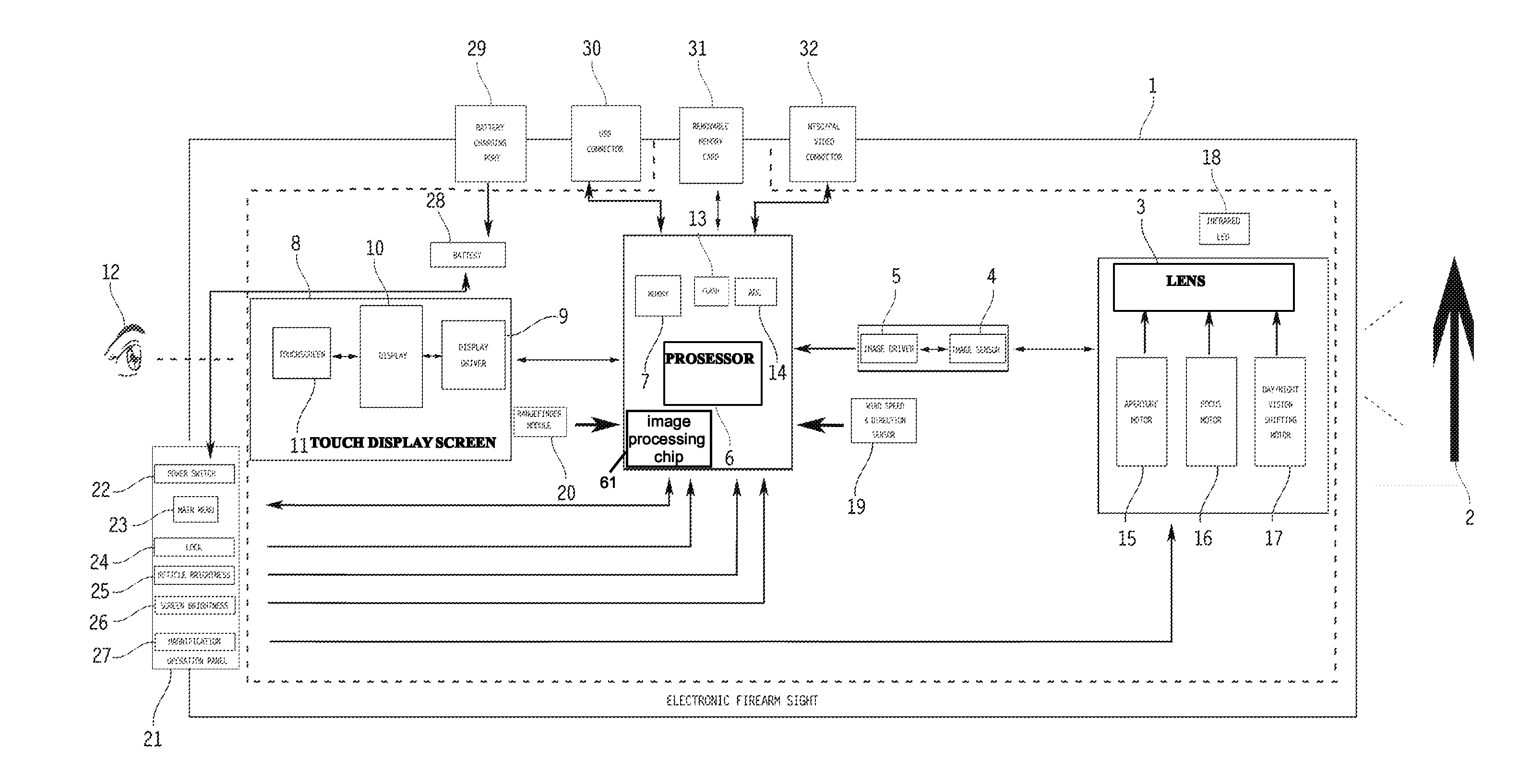
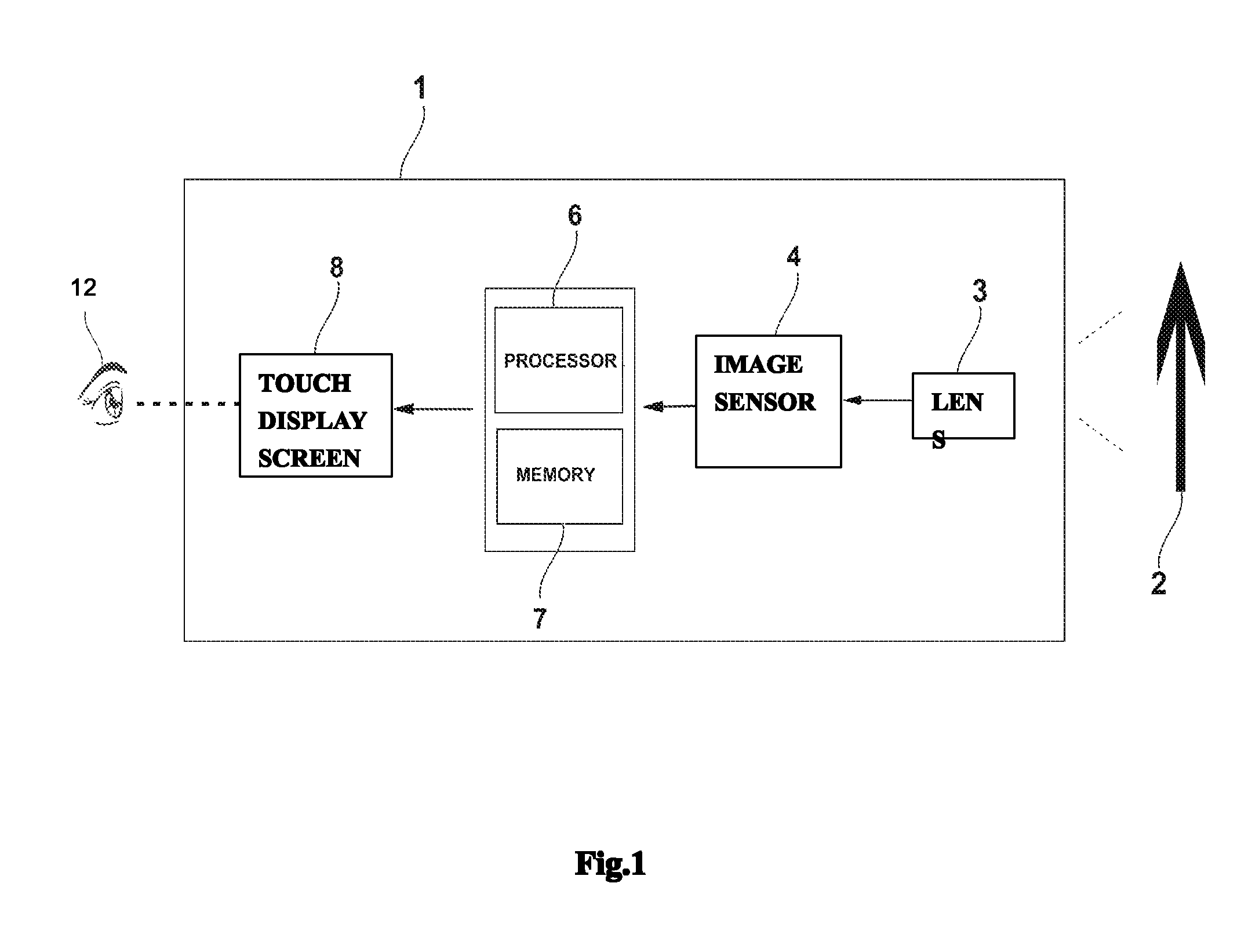
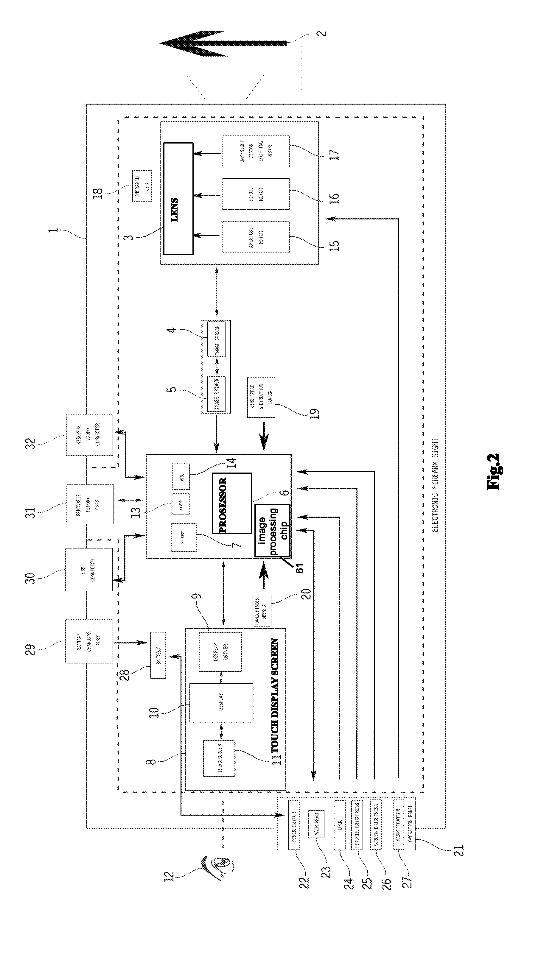
[0047]As shown in FIG. 1, an electronic firearm sight 1 comprises a set of optical lens 3, which captures the image of an object 2, an image sensor 4 connected with the set of optical lens 3, which converts lights into charges, a processor 6 connected with the image sensor 4, which processes the image from the image sensor 4, a memory 7 connected with the processor 6, which stores a variety of information ready to be processed or having processed by the processor, and a touch display screen 8, which receives operation instructions given by a user 9 and sends corresponding information to the processor, the processor analyzing and processing the information, and then sending it back to and having it displayed on the touch display screen.

[0048]Referring to FIG. 2, The lens 3 is a multiple of zoom lens, which can change the focus through changing the relative places of the lens, so that make the views at distance clearer. The lens 3 could be wide-angle lens, standard lens, telephoto len...


PUM


Abstract

A touch display screen used for adjusting and determining the reticle of an electronic firearm sight, includes: a display; a touch screen installed in front of the display; and a display driver. The touch display screen is connected with a processor, the processor in turn is connected with a memory; the memory is provided with pre-saved data of a Cartesian coordinate system, ballistic trajectory data of different bullets and reticle scales formed based on different ballistic trajectories of different bullets; the touch display screen receives operations of adjusting the reticle from a user and sends corresponding information to the processor; the processor analyzes the information through using the pre-saved data in the memory, forms commands, and sends the commands to the touch display screen to execute.

Description

CROSS REFERENCE OF RELATED APPLICATION[0001]This is a divisional application of U.S. patent application Ser. No. 12 / 911,525, filed Oct. 25, 2010, which claims priority under 35 U.S.C. 119(a-d) to CN 201010511597.8, filed Oct. 19, 2010.BACKGROUND[0002]1. Field of the Invention[0003]The present invention relates to the field of firearm sights, more particularly, to a touch display screen used for adjusting and determining the reticle of an electronic firearm sight.[0004]2. Brief Description of Related Arts[0005]Over times, people invented a variety of instruments and devices to help shooters to aim at a target. In general, the conventional sighting devices used in firearms can be categorized into telescopic sight, reflex sight and other sights based upon different principles.[0006]To achieve the goal of aiming at a potential target accurately, rapidly and conveniently, a reticle is a very important factor to locate the target. Other auxiliary aides, such as measuring the range, can be...

Claims


Application Information

Patent Timeline
Patent Type & Authority Applications(United States)
IPC IPC(8): F41G1/00
CPCF41G1/00F41G1/38F41G1/473F41G3/06F41G3/08F41G3/142F41G3/165
Inventor LI, DANYUN
Owner LI DANYUN
Why Eureka
Try Eureka