
Roof solar panel for conventional sloping roof and shingle integration

a solar panel and conventional sloping roof technology, applied in sheet joining, photovoltaics, solar heat collectors for particular environments, etc., can solve the problems of undesirable profile and aesthetic factors, specialized and costly structure of roof panels, and requiring specialized installation

Active Publication Date: 2014-03-27
RICHARDSON ROBERT
View PDF54 Cites 28 Cited by
  • Summary
  • Abstract
  • Description
  • Claims
  • Application Information

AI Technical Summary

Benefits of technology

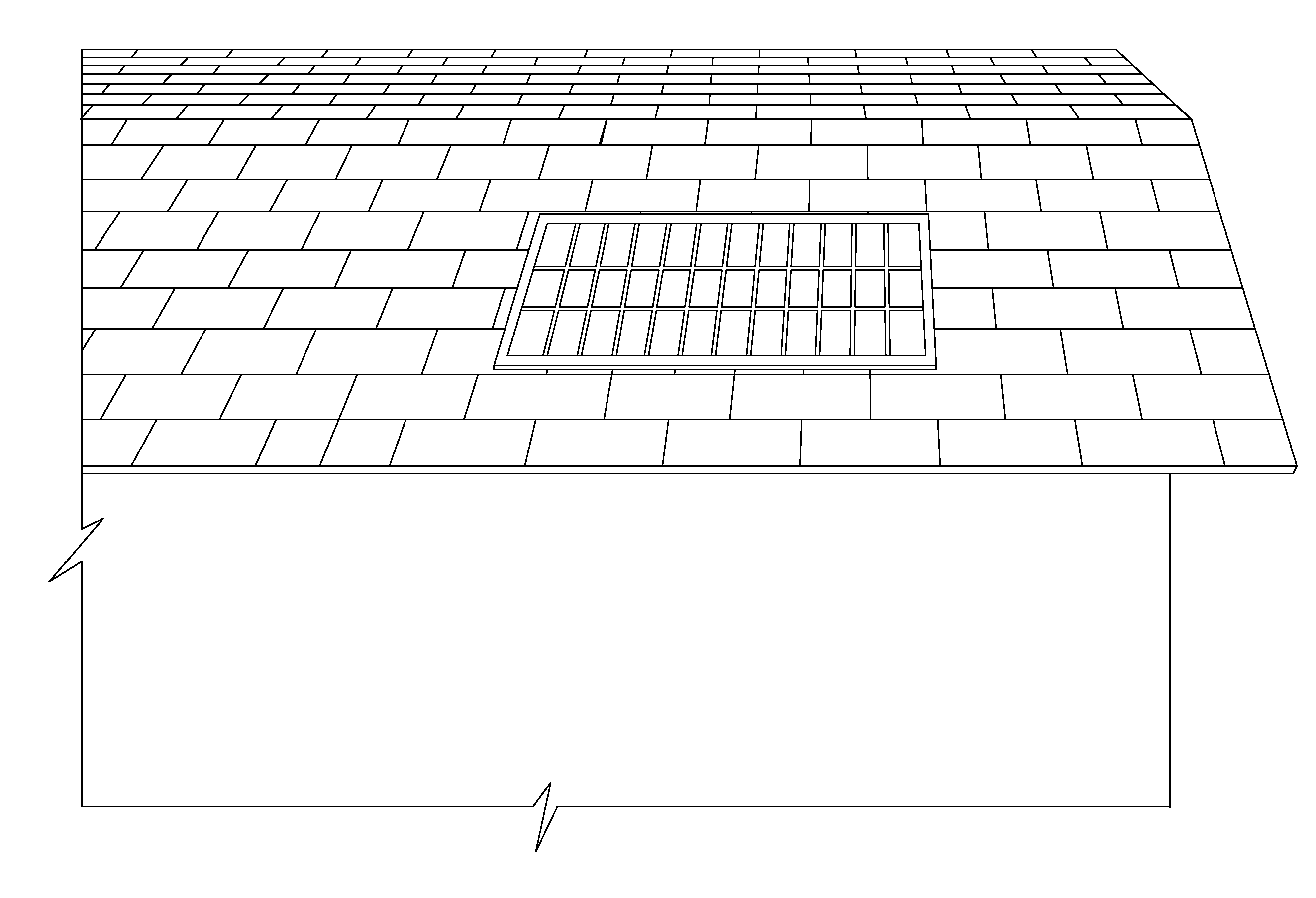
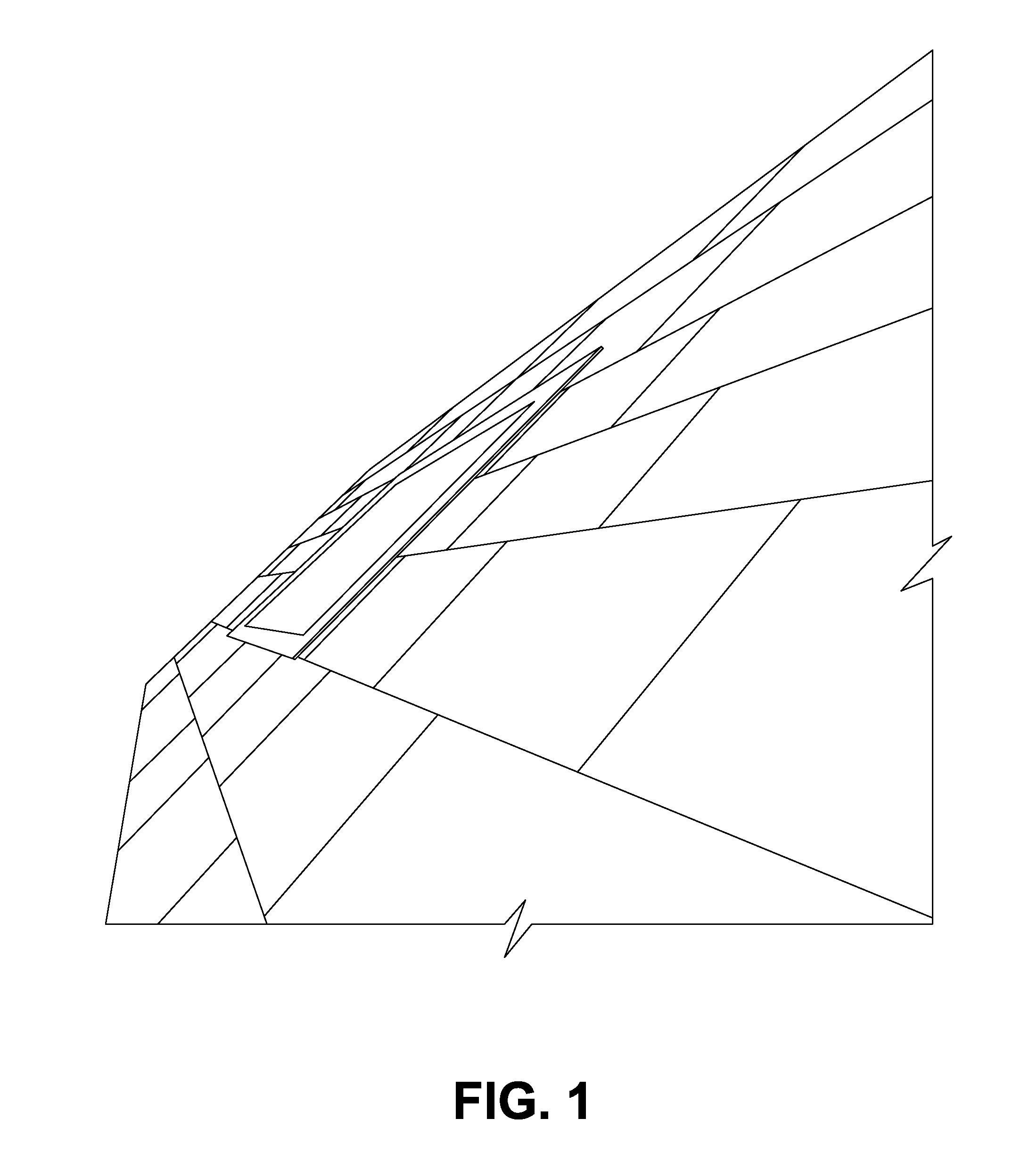
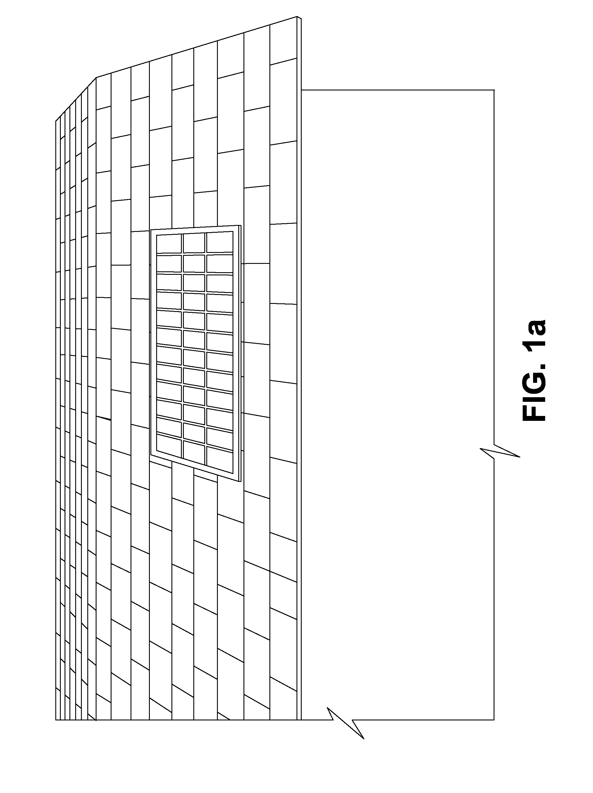
The invention provides a modular roof solar panel that can be installed on a sloping roof. The panel includes modular roof sheathing with an upper surface and a sheathing perimeter. A flashing strip is mounted on the sheathing perimeter and has an inside and outside perimeter edge. A protective sheet is mounted on the flashing strip and sealed to the flashing strip and the roof sheathing. The panel also includes a retainer trim that is mounted on the shingle mounting surface and seals with a retaining lip on the protective sheet. The technical effects of the invention include providing a solar panel that is easy to install, efficient in use of space, and aesthetically pleasing.

Problems solved by technology

However, structural roof panels are generally of specialized and costly configuration and installation, often complex and / or heavy and requiring modification or replacement of existing conventional roof structures.
The combination of non-structural substrates and solar panels is also well known as substitutes for roofing materials such as shingles and tiles, but such are also typically costly and requiring specialized installation.
Solar panels for installation over existing roof components are also well known, but such pose undesirable profile and aesthetic factors, and challenges for mounting securely on the roof without compromising existing roof components or their function.

Method used


Image

  • Roof solar panel for conventional sloping roof and shingle integration
  • Roof solar panel for conventional sloping roof and shingle integration
  • Roof solar panel for conventional sloping roof and shingle integration

Examples


Embodiment Construction

[0024]There is disclosed herein a prefabricated intermediate roof solar panel that is configured to be installed onto conventional roof trusses, a method of installing such roof solar panel and the resulting finished roof solar panel after such installation. The intermediate roof solar panel is comprised of a substrate which is preferably either conventional (structural) roof sheathing such as 4′×8′ plywood, or a non-flammable substitute. The sheathing supports a conventional photovoltaic cell array sealed onto much of its upper surface and covered by a rigid, transparent protective sheet such as glass, plexiglass, or most preferably low iron glass. Such protective sheet is for protecting the array from the usual physical stresses caused by weather (wind, water, snow etc.) and atmospheric debris, while allowing sunlight to pass through to the surface of the photovoltaic array for conversion into electricity. A flashing strip is mounted around a perimeter area of the sheathing and th...


PUM


Abstract

There is provided an improved roof solar panel, embodying an array of photovoltaic cells mounted on conventional modular roof sheathing, that can be readily and easily installed onto a conventional sloped roof and integrated into conventional roof shingles. Such panel includes a shingle mounting surface on a perimeter area of the sheathing, a flash strip mounted inside such shingle mounting surface and, when installed on the roof, a retainer trim for securing shingles mounted on said shingle mounting surface, while mounting to the flash strip and sealing to a perimeter of a rigid transparent protective sheet over the array. The retainer trim also serves to provide means for securing the panel onto roof trusses. Integration with the conventional roof shingling provides, inter alia, an attractive low profile with improved water shedding and wind resistance properties. There is also an intermediate roof solar panel, for installation on a roof so as to provide the aforementioned improved roof solar panel. The invention also relates to a kit comprising, inter alia, said intermediate roof solar panel, and to a method of installing said intermediate roof solar panel.

Description

FIELD OF THE INVENTION[0001]The present invention relates to an improved roof solar panel, embodying photovoltaic cells, that can be readily and easily installed into a conventional sloping roof and that integrates with a conventional shingle finish on the roof so as to provide, inter alia, an attractive low profile with improved water shedding and wind resistance properties. Further, the invention relates to an intermediate roof solar panel, for installation so as to provide the aforementioned improved roof solar panel. The invention also relates to a kit comprising, inter alia, said intermediate roof solar panel, and to a method of installing said intermediate roof solar panel.BACKGROUND[0002]Both non-structural and structural roof elements incorporating solar collectors such as an array of photovoltaic cells are well known. However, structural roof panels are generally of specialized and costly configuration and installation, often complex and / or heavy and requiring modification ...

Claims


Application Information

Patent Timeline
Patent Type & Authority Applications(United States)
IPC IPC(8): F24J2/52H02S20/23
CPCF24J2/5245F16B5/0635F16B11/006F24S20/67F24S25/61F24S40/10F24S2025/014F24S2025/6005F24S2025/601H02S20/23Y02B10/10Y02B10/20Y02E10/47Y02E10/50Y02E10/44
Inventor RICHARDSON, ROBERT
Owner RICHARDSON ROBERT
Learn More