Radio frequency identification module

a technology of radio frequency identification and module, which is applied in the field of radio frequency identification (rfid) modules, can solve the problems of increasing the size of the transponder, unable to function as the reader to identify devices, and only being able to identify the conventional sim unilaterally

Inactive Publication Date: 2014-04-03
SMART APPROACH
View PDF5 Cites 1 Cited by
  • Summary
  • Abstract
  • Description
  • Claims
  • Application Information

AI Technical Summary

Problems solved by technology

In other words, the conventional SIM could only be unilaterally identified, which is not able to function as the reader to identify devices external to the SIM such as a smart card.
Moreover, the electronic chip in the conventional transponder is placed outside a region surrounded by the antenna, which increases the size of the transponder.

Method used


Image

  • Radio frequency identification module
  • Radio frequency identification module
  • Radio frequency identification module

Examples


first embodiment

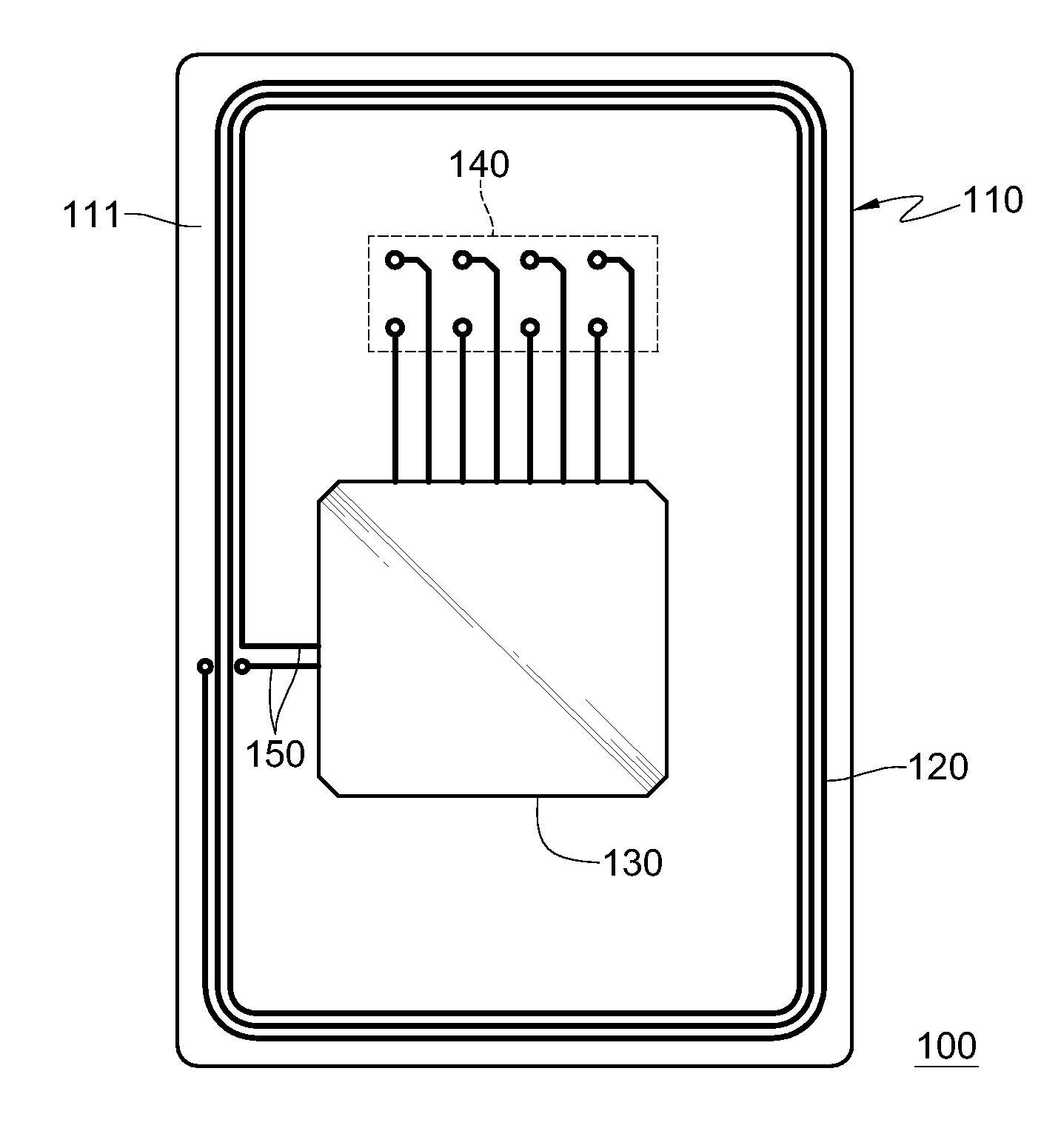
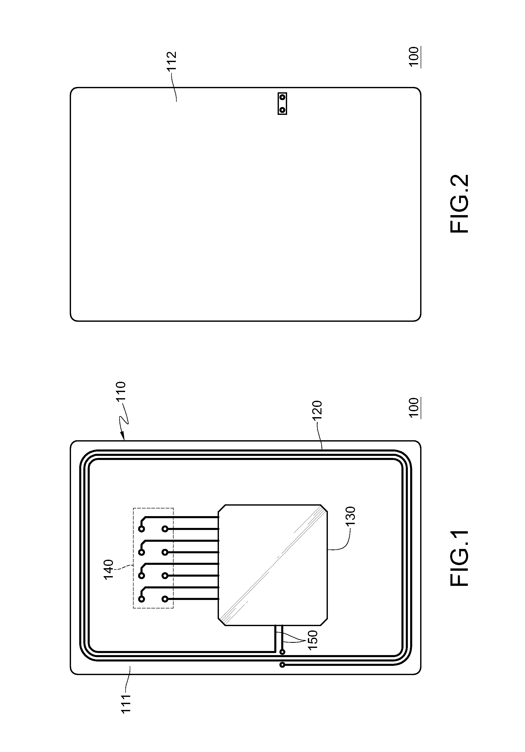
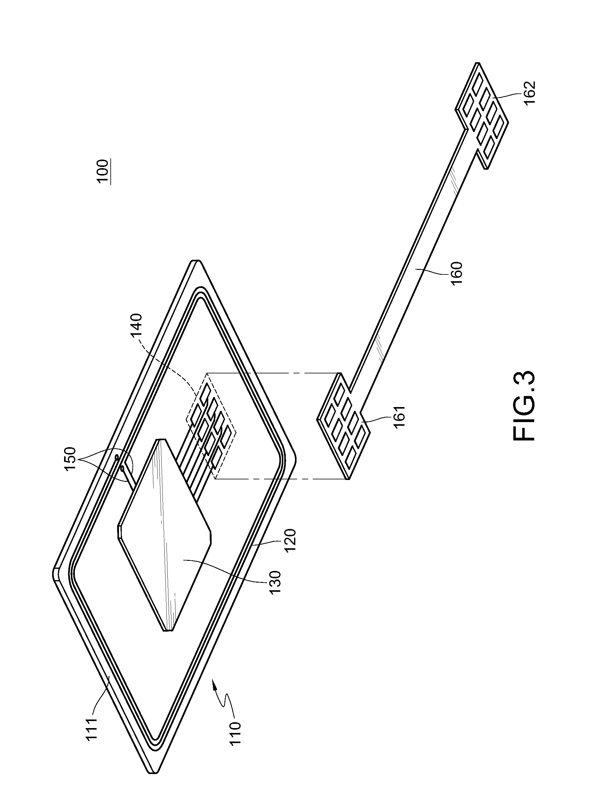
[0021]Please refer to FIGS. 1 and 2, which are a top view and a bottom view of a radio frequency identification (RFID) module 100 according to the disclosure, respectively. The RFID module 100 may be placed into a cellular phone, a laptop / notebook, a portable application description (PAD) device, an RF-related device, or a near-field communication device for facilitating the RFID-based communication or enhancing the near-field communication.

[0022]The RFID module 100 comprises a substrate 110, an antenna coil 120, an identification module 130, and multiple connection points 140. In this embodiment, the substrate 110 may be a flexible substrate, i.e., a flex printed circuit board (FPC).

[0023]The antenna coil 120 is disposed on the substrate 110 in a printed manner. The antenna coil 120 may be an RF-based antenna or a near-field communication antenna.

[0024]The identification module 130 is disposed on the substrate 110 and placed in a predetermined region of the substrate 110. The prede...

second embodiment

[0034]Please refer to FIGS. 4 and 5, which are a top view and a bottom view of an RFID module according to the disclosure, respectively. An RFID module 200 comprises a substrate 210, an antenna coil 220, an identification module 230, multiple connection points 240 and a connection wire 250. Structures of the substrate 210, the antenna coil 220, the identification module 230, the connection points 240, and the connection wire 250 may be the same as their counterparts in FIGS. 1 and 2, so the similarities are not repeated again. Similarly, the RFID module 200 also comprises the same bus shown in FIG. 3 so that the connections points 240 are electrically connected to the control chip of the handheld electronic device through the bus, and the similarities are not repeated, either.

[0035]In this embodiment, the substrate 210 includes a first surface 211 and a second surface 212 which are opposite to each other. The antenna coil 220 is disposed on the first surface 211 of the substrate 210...


PUM


Abstract

AN RFID module includes a substrate, an antenna coil, an identification module, and multiple connection points. The antenna coil is placed on the substrate. The identification module is disposed on the substrate and within a predetermined region surrounded by the antenna coil. The identification module is electrically connected to the antenna coil. The connection points is disposed on the substrate and electrically connected to the identification module.

Description

CROSS-REFERENCE TO RELATED APPLICATIONS[0001]This non-provisional application claims priority under 35 U.S.C. §119(a) on Patent Application No(s). 101218891 filed in Taiwan, R.O.C. on Sep. 28, 2012, the entire contents of which are hereby incorporated by reference.BACKGROUND[0002]1. Technical Field[0003]The disclosure relates to a radio frequency identification (RFID) module, and more particularly, to an RFID module in a reduced size.[0004]2. Related Art[0005]With the wireless transmission technology advancing, subscriber identity modules (SIM) of handheld electronic devices are beginning to have an RFID-related technology integrated. Architecture of the RFID-related technology mainly includes a reader, a transponder and a middleware / system integration. When the RFID-related technology is integrated with the SIM of the handheld electronic devices, the handheld electronic devices are enabled to have the RFID capability.[0006]The reader includes a signal processing unit and a wireless...

Claims


Application Information

Patent Timeline
Patent Type & Authority Applications(United States)
IPC IPC(8): G06K19/07
CPCG06K19/0723G06K7/10237G06K19/07749G06K19/07769
Inventor LIN, HSIN-LUNGLIN, MING-CHUNG
Owner SMART APPROACH
Why Eureka
Try Eureka