Lighting system

a technology of lighting system and light source, which is applied in the direction of electric variable regulation, process and machine control, instruments, etc., can solve the problems of inability to handle color temperature, difficulty in knowing the correspondence relationship between lighting devices and faders, and complex operation

Active Publication Date: 2014-04-03
PANASONIC INTELLECTUAL PROPERTY MANAGEMENT CO LTD
View PDF3 Cites 36 Cited by
  • Summary
  • Abstract
  • Description
  • Claims
  • Application Information

AI Technical Summary

Benefits of technology

[0006]In view of the above, the present invention provides a lighting system that enables a general user to intuitively set the scene setting information for changing the lighting states of lighting devices, while imaging a target area in which the lighting devices are arranged.

Problems solved by technology

However, the dimming console disclosed in JP 2000-311791A involves the complexity in operation and a difficulty in knowing the correspondence relationship between the lighting devices and the faders.
However, the lighting setting device disclosed in JP 2006-277972A is used in setting the luminous intensities of the lighting devices arranged on the ceiling of a building but is not intended for use in the lighting of a living room of a general house.
However, the lighting control system disclosed in JP 2006-277972A mainly displays the schedule on the dimming ratio and fails to handle the color temperature.
For that reason, it is not easy for a general user to perform, with respect to a plurality of lighting devices, the scene setting by which the lighting states such as the dimming ratio and the color temperature are changed over time.

Method used


Image

  • Lighting system
  • Lighting system
  • Lighting system

Examples


Embodiment Construction

[0047]A lighting system in accordance with one embodiment of the present invention will now be described with reference to the accompanying drawings.

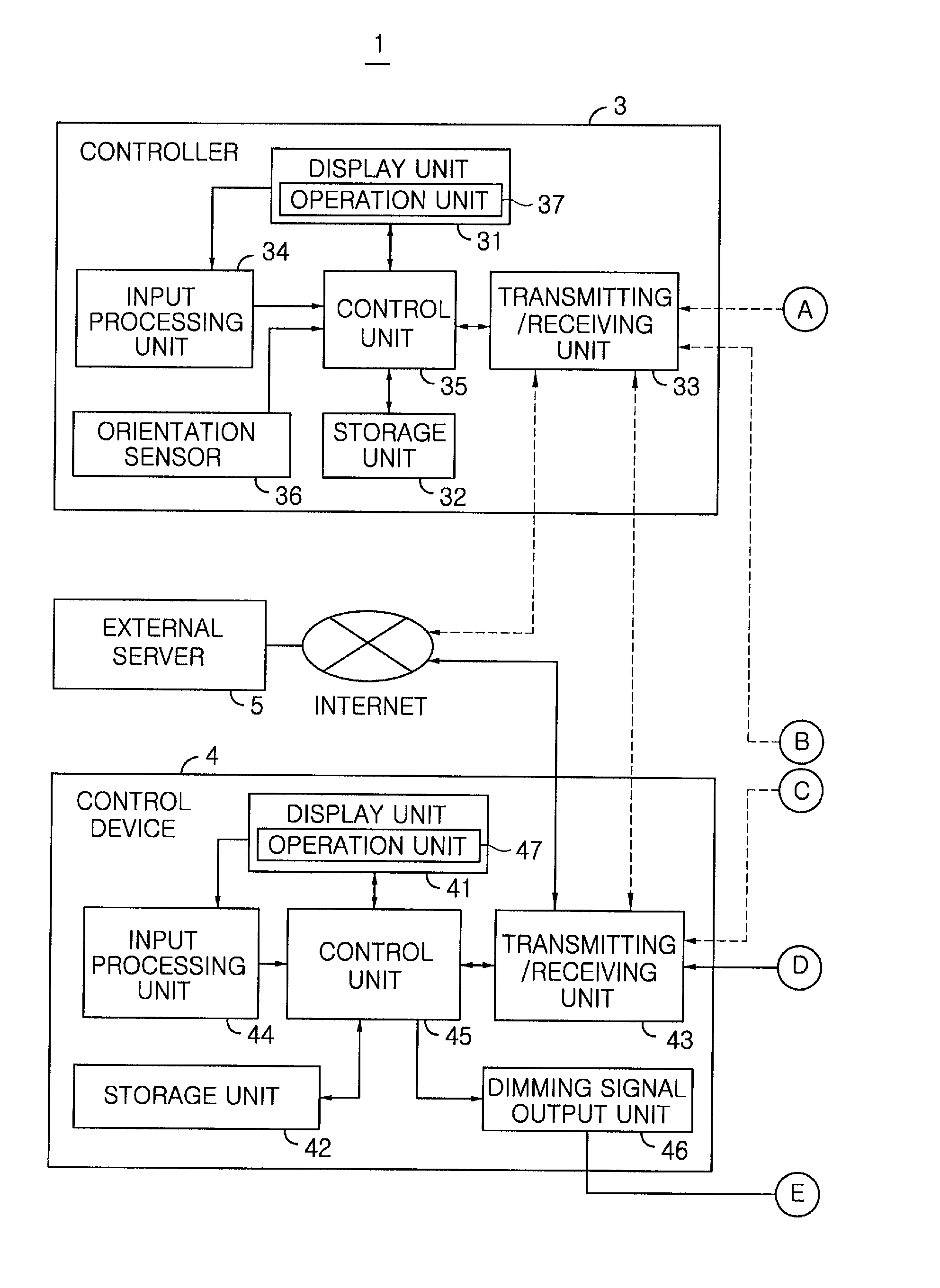
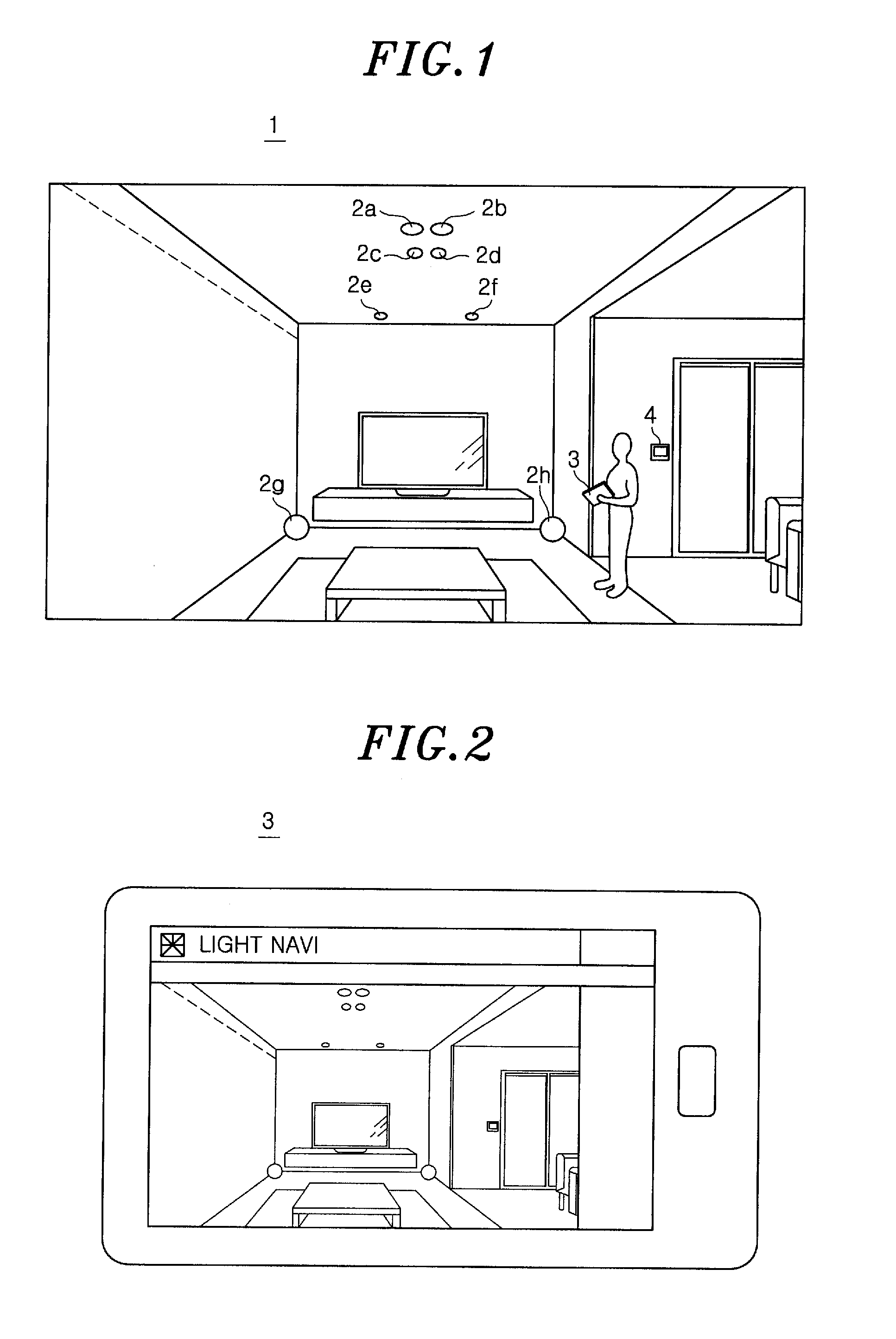
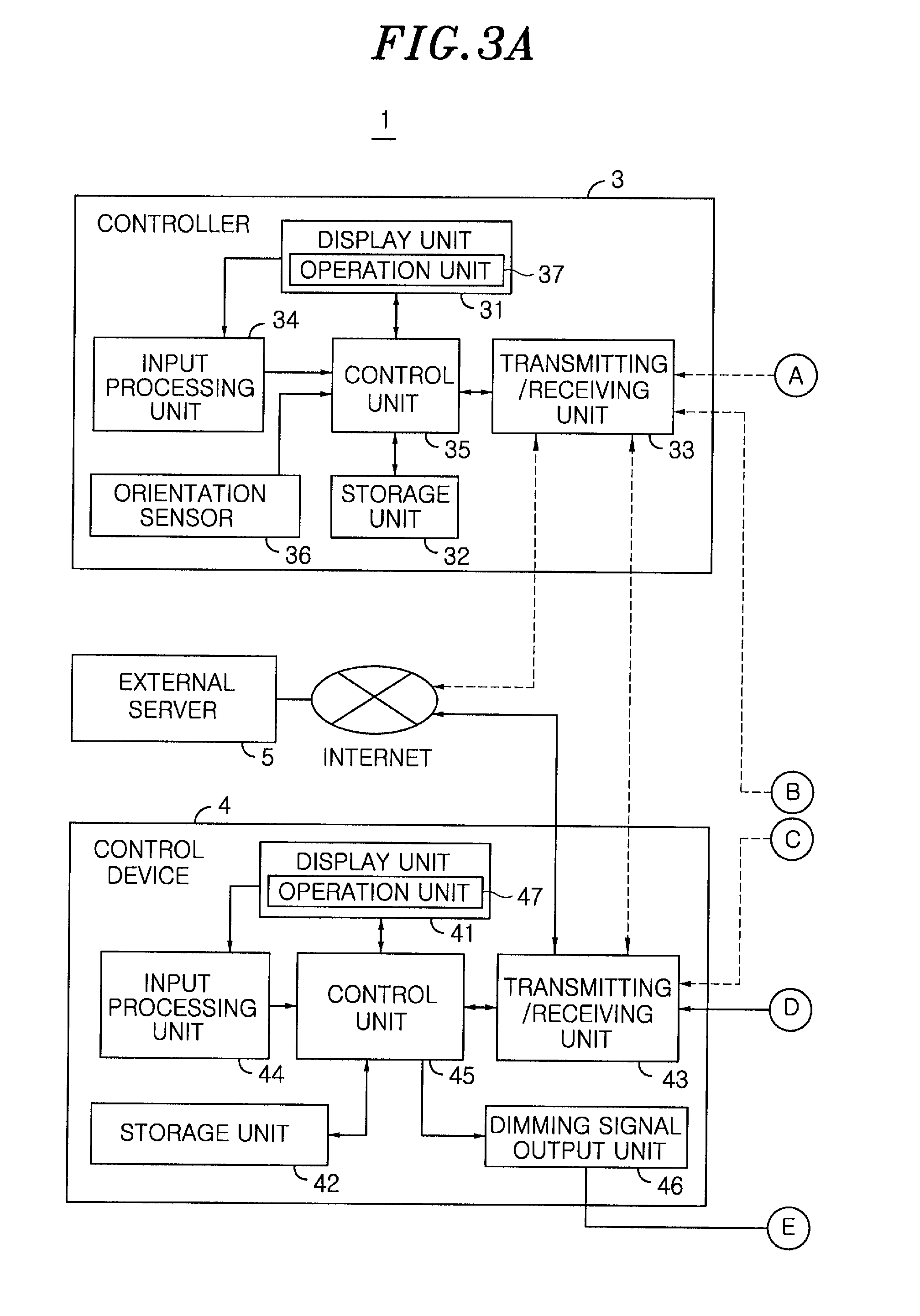
[0048]Referring to FIG. 1, the lighting system 1 includes a plurality of lighting devices 2a to 2h (hereinafter collectively referred to as “lighting devices 2”) and a controller 3 for setting the lighting control contents of the lighting devices 2. The lighting system 1 is applicably used within a general house or within a building. In the present embodiment, the lighting system 1 further includes a control device 4 for turning on / off the lighting devices 2 in response to a control signal sent from the controller 3. However, the control device 4 may be omitted in a case where all the lighting devices 2 can be directly controlled by the controller 3.

[0049]Each of the lighting devices 2 has its own identification information. If the identification information and lighting control contents (lighting information) of the lighting devices 2,...


PUM


Abstract

The lighting system includes lighting devices and a controller of the lighting devices. The controller includes a display unit and a storage unit which stores area information including target areas in which the lighting devices are arranged, the identification information of the lighting devices, the lighting information regarding different lighting conditions of the lighting devices, and scene setting information regarding a state change pattern for changing a lighting state of one or more lighting devices allotted to each target area. The control unit controls the display unit to display a scene operation screen having pictorial signs each indicating one piece of scene setting information, and selects, if one of the pictorial signs is touched, a corresponding scene setting information represented by the pictorial sign, and controls the display unit to display a state change pattern of each lighting device allotted to the selected piece of scene setting information.

Description

FIELD OF THE INVENTION[0001]The present invention relates to a lighting system for controlling a plurality of lighting devices in accordance with the control contents set by a controller.BACKGROUND OF THE INVENTION[0002]There is conventionally available a lighting setting device capable of performing lighting scene production by arbitrarily setting, depending on the intended use, the luminous intensities of lighting devices arranged within a room, the illuminances in the respective positions within a building, or the like. In order to create the lighting scenes, there has been used a dimming console provided with a plurality of faders for setting the output level of a specified dimming control signal with respect to each of the channels corresponding to the dimmers respectively connected to a plurality of lighting devices (see, e.g., JP 2000-311791A).[0003]However, the dimming console disclosed in JP 2000-311791A involves the complexity in operation and a difficulty in knowing the c...

Claims


Application Information

Patent Timeline
Patent Type & Authority Applications(United States)
IPC IPC(8): H05B33/08H05B44/00
CPCH05B33/0845H05B33/0863H05B47/175H05B47/155H05B45/20
Inventor FUSHIMI, SHIGEMI
Owner PANASONIC INTELLECTUAL PROPERTY MANAGEMENT CO LTD
Why Eureka
Try Eureka