Cartridge and image forming apparatus

Active Publication Date: 2014-04-03
CANON KK
View PDF9 Cites 12 Cited by
  • Summary
  • Abstract
  • Description
  • Claims
  • Application Information

AI Technical Summary

Benefits of technology

[0008]Therefore, a principal object of the present invention is to provide a cartridge and an image forming apparatus which are capable of improving a sealing property while suppressing an increase in size of a seal member.
[0009]According to an aspect of the present invention, there is provided a cartridge detachably mountable to a main assembly of an image forming apparatus, comprising: a frame; an accommodating portion, constituted by the frame, for accommodating a developer; a seal portion for preventing the developer from being leaking out from the accommodating portion, wherein the seal portion is formed by injection molding at a seal forming portion provided on the frame and is projected from the seal forming portion; and a sprue which is formed integrally with the seal portion by a resin material remaining in a path for permitting flow of the resin material melted when the seal portion is formed by the injection molding and which is projected from the frame in a position

Problems solved by technology

However, in this conventional proposal, there was the following problem.
That is, in the case where the seal member is molded on the cartridge frame by using the two-color molding, due to a constraint

Method used


Image

  • Cartridge and image forming apparatus
  • Cartridge and image forming apparatus
  • Cartridge and image forming apparatus

Examples


embodiment 1

[0045]

[0046]Next, with reference to FIGS. 3 to 7, a seal structure of the developing unit 2b in Embodiment 1 will be described.

[0047]FIG. 3 is a schematic sectional view showing a seal structure of a developing unit in this embodiment. FIG. 4 is a schematic front view before a under-developing-blade seal is molded on a developing (device) frame in this embodiment. FIG. 5 is a schematic front view after the under-developing-blade seal is molded on the developing frame in this embodiment. Parts (a) and (b) of FIG. 6 are schematic sectional views of the under-developing-blade seal taken along A-A line indicated in Embodiment 5, wherein (a) of FIG. 6 shows a state before the developing blade unit is connected, and (b) of FIG. 6 shows a state in which the developing blade unit is connected. FIG. 7 is a schematic sectional view showing a seal mold of the under-developing-blade seal in this embodiment.

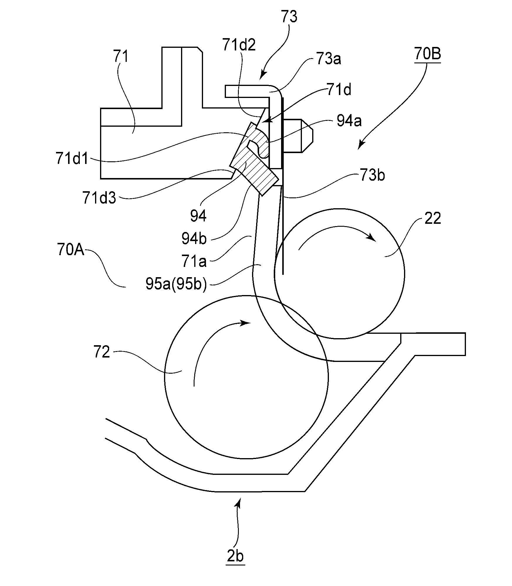
[0048]As shown in FIG. 3, the developing portion 70B includes a developing opening 71a fo...

embodiment 2

[0065]Next, Embodiment 2 will be described with reference to FIGS. 14 to 16. FIG. 14 is a schematic sectional view of a seal structure of a developing frame in this embodiment. FIG. 15 is a schematic perspective view of the seal structure of the developing frame in this embodiment. Parts (a) and (b) of FIG. 16 are schematic sectional views of a frame seal portion of the developing frame in this embodiment, wherein (a) shows a state before a developing frame member is connected, and (b) shows a state in which the developing frame member is connected. In this embodiment, a frame seal 96 as a seal member for sealing between developing frame members 78 and 79 each being a part of the developing frame 71 is formed of the elastomer resin material.

[0066]As shown in FIGS. 14 and 15, the frame seal 96 includes a seal function portion 96a as the seal portion and a sprue 96b as the molded portion. The seal function portion 96a is formed at a seal forming portion 78a of the developing frame mem...

embodiment 3

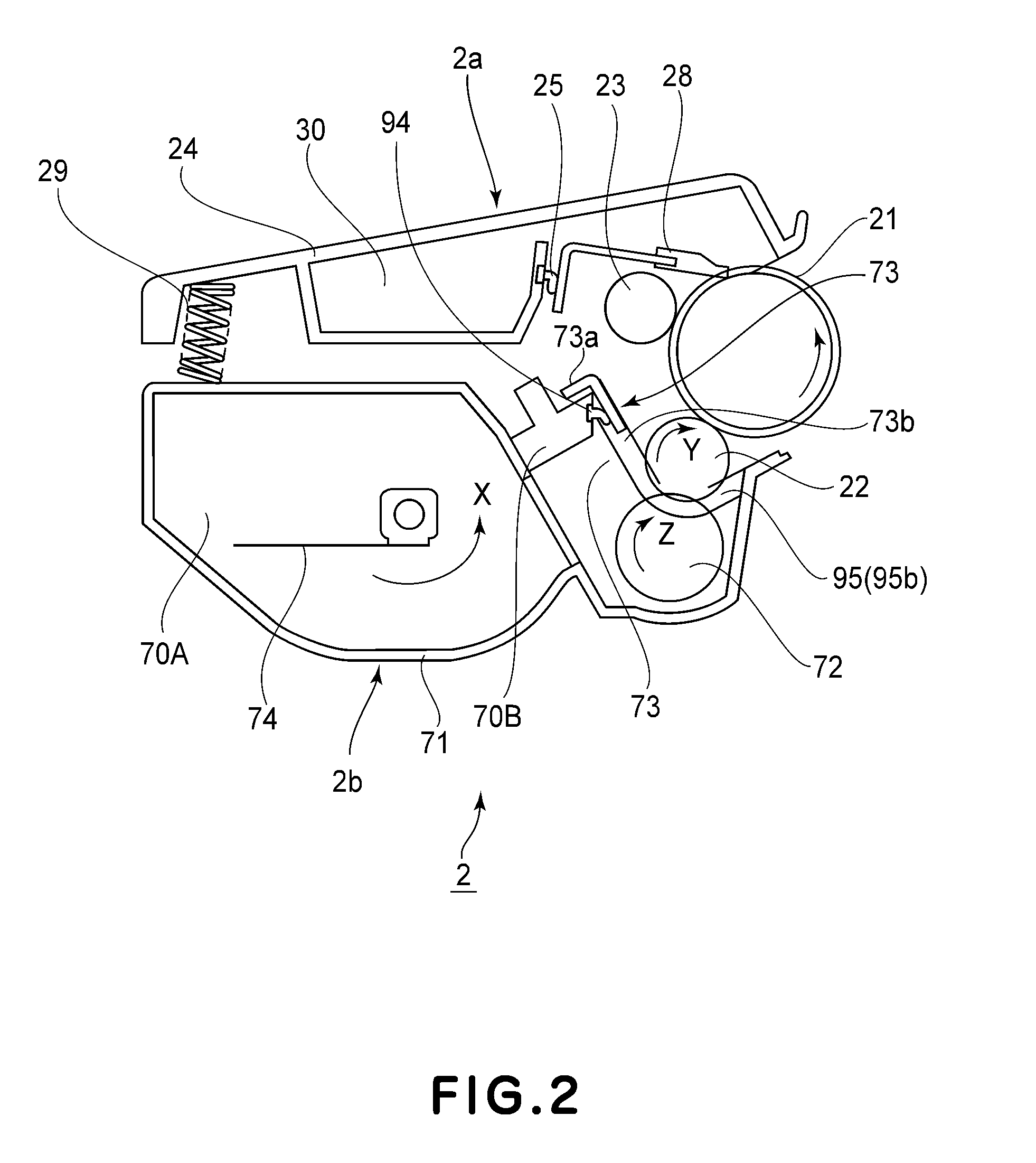
[0071]Next, Embodiment 3 will be described. In Embodiment 1, the under-developing-blade seal 94 of the developing unit 2b shown in FIG. 2 was described, but the present invention is also applicable to a under-cleaning-blade seal 25 of the photosensitive drum unit (cleaning unit) 2a. That is, the under-cleaning-blade seal 25 as a seal member provided between the cleaning frame 24 and a cleaning blade 28 as a connected member connected with the cleaning frame 24 has the following constitution.

[0072]The under-cleaning-blade seal 25 is formed by bringing a mold into contact with the cleaning frame 24 and then by injecting the resin material onto the mold. The under-cleaning-blade seal 25 includes a seal function portion as a seal portion and a sprue as a molded portion. By providing such a under-cleaning-blade seal 25, it is possible to prevent the toner from leaking out from between the cleaning frame 24 and the cleaning blade 28.

[0073]In the process cartridge 2 including the under-cle...


PUM


Abstract

A cartridge detachably mountable to a main assembly of an image forming apparatus includes: a frame; an accommodating portion, constituted by the frame, for accommodating a developer; a seal portion for preventing the developer from being leaking out from the accommodating portion, wherein the seal portion is formed by injection molding at a seal forming portion provided on the frame and is projected from the seal forming portion; and a sprue which is formed integrally with the seal portion by a resin material remaining in a path for permitting flow of the resin material melted when the seal portion is formed by the injection molding and which is projected from the frame in a position different from a position of the seal portion so as to be higher than the seal portion on the basis of the frame.

Description

FIELD OF THE INVENTION AND RELATED ART[0001]The present invention relates to a process cartridge detachably mountable to an image forming apparatus and relates to the image forming apparatus.[0002]In an electrophotographic image forming apparatus using an electrophotographic image forming process, an electrophotographic photosensitive member and a process means actable on the photosensitive member are integrally assembled into a unit to prepare a process cartridge. Further, a type in which this process cartridge is made detachably mountable to a main assembly of the image forming apparatus is employed.[0003]In such a process cartridge, in order to prevent leakage of a developer (toner) to an outside of the process cartridge, a constitution in which sealing with a plurality of seal members is made between cartridge frames constituting the process cartridge and between parts constituting the process cartridge is employed.[0004]As the seal member, an elastic member such as an urethane ...

Claims


Application Information

Patent Timeline
IPC IPC(8): G03G15/08
CPCG03G21/1803G03G21/1828G03G15/0817G03G15/0898
Inventor HOSHI, NOBUHARU
Owner CANON KK
Why Eureka
Try Eureka