
Punching bag support apparatus

a support apparatus and bag technology, applied in the field of punching bag support apparatus, to achieve the effect of sufficient stability for repetitive striking

Active Publication Date: 2014-04-03
SAGALL JASON
View PDF0 Cites 12 Cited by
  • Summary
  • Abstract
  • Description
  • Claims
  • Application Information

AI Technical Summary

Benefits of technology

The invention allows for easy installation of a punching bag on multiple buildings by using existing doors frames and other structural elements with no damage to them. This results in stable support for repeatedly hitting the punching bag.

Problems solved by technology

The technical problem addressed in this patent is the need for a punching bag support apparatus that can provide stable and effective support for a variety of punching bags, including speed bags and heavy bags, without causing damage or safety hazards to the supporting structures and without causing markings or indentations to the supporting structures. The apparatus should also be able to achieve a level of stability and performance required for speed bag use, including the use of a solid rebound platform or high-rebound and low-vibration characteristics. Previous references have failed to provide such a support apparatus that meets all of these requirements.

Method used


Image

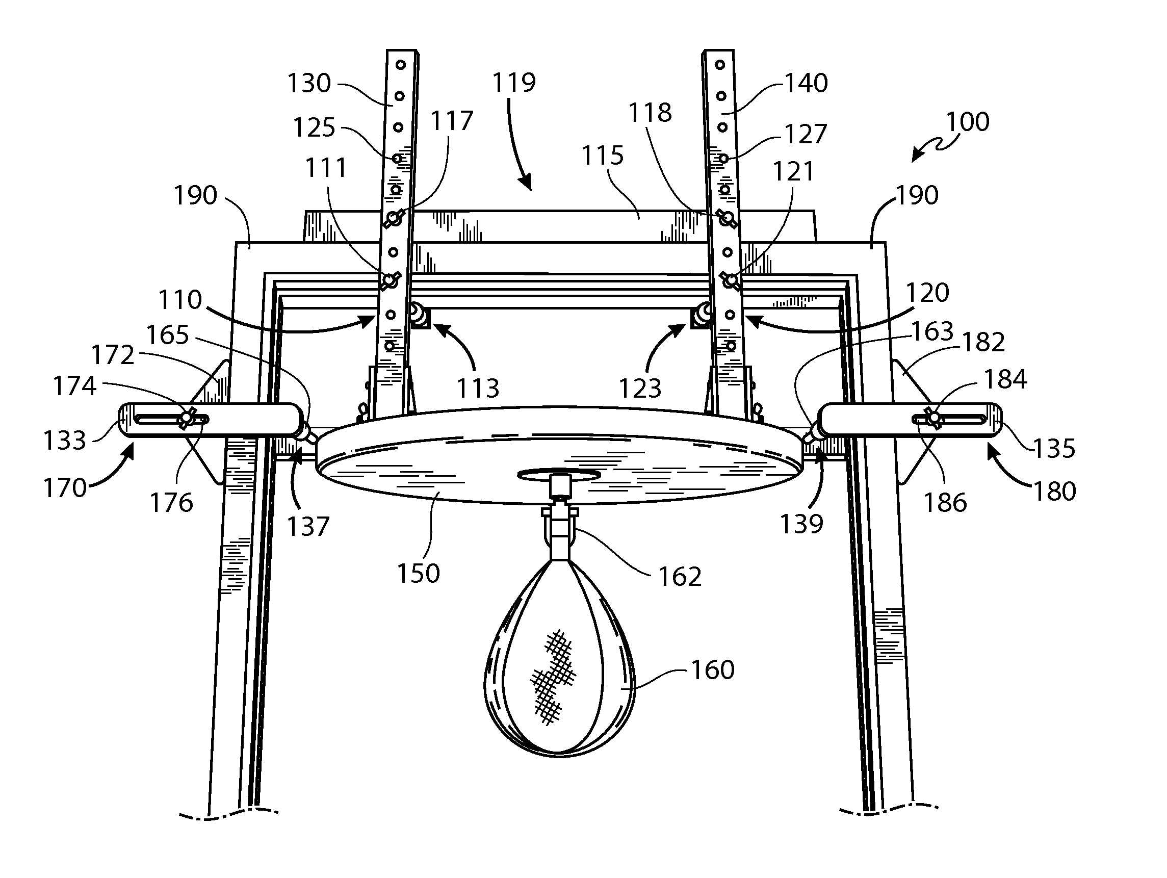
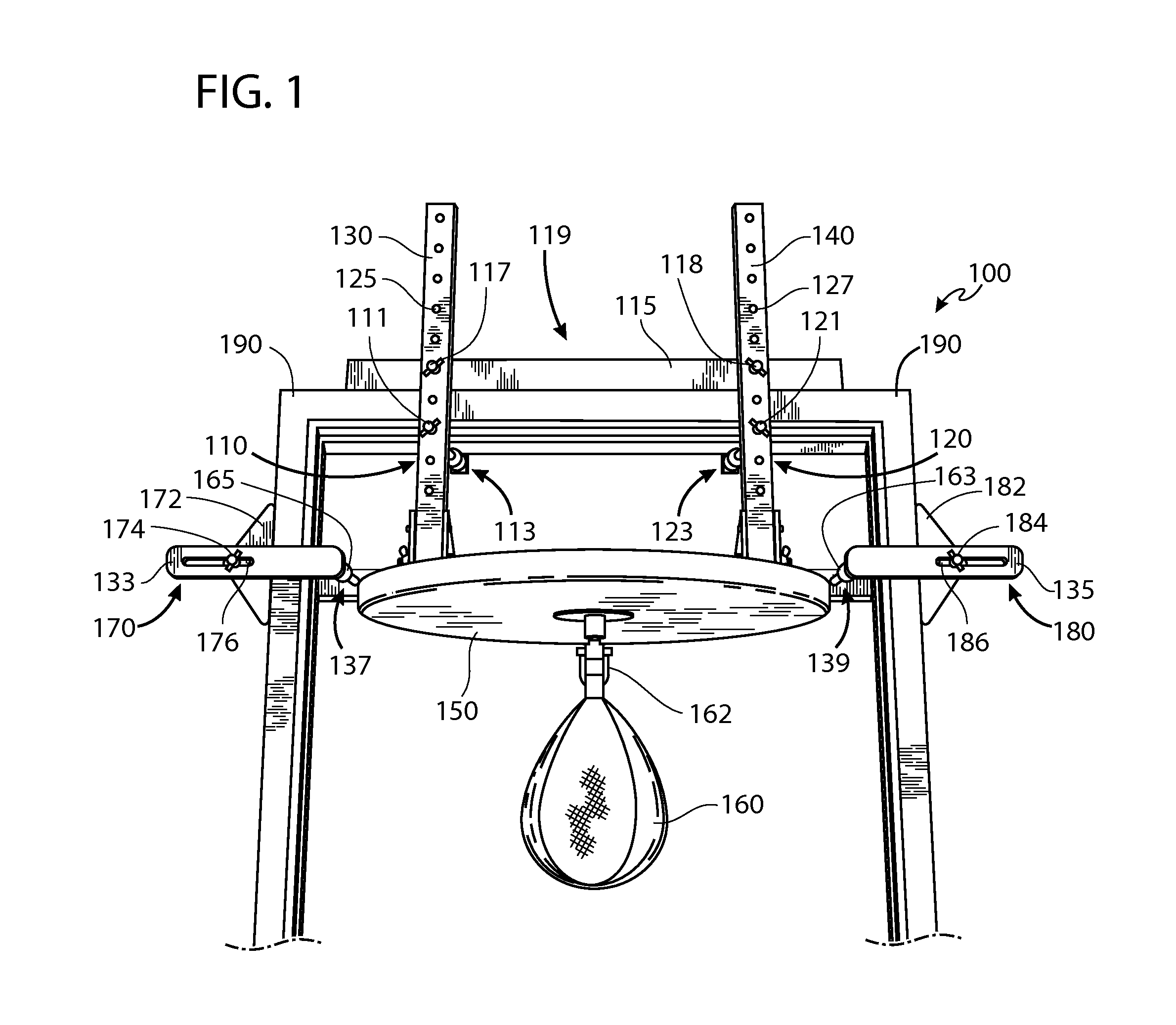
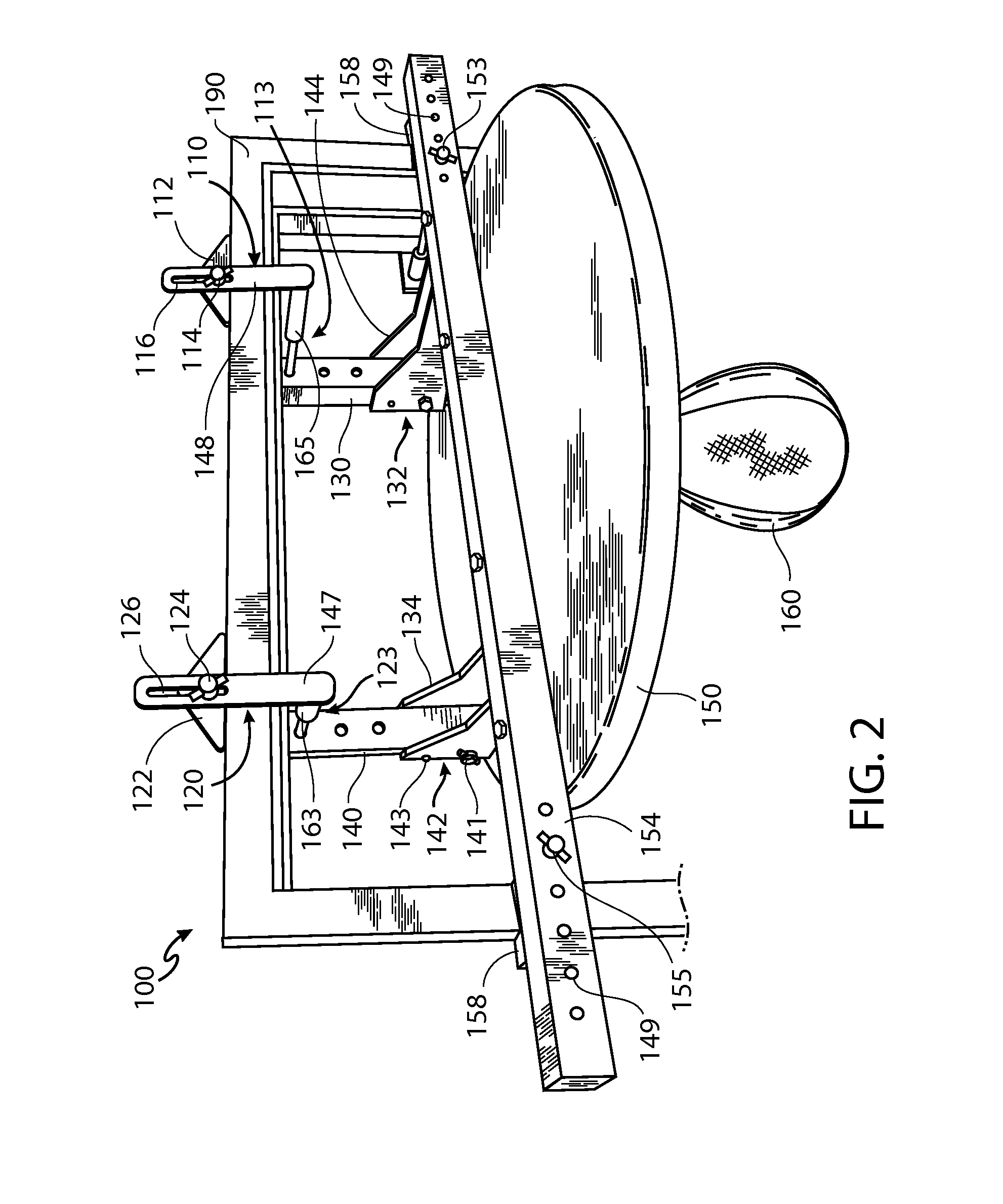
  • Punching bag support apparatus
  • Punching bag support apparatus
  • Punching bag support apparatus

Examples


Embodiment Construction

[0043]Previous support methods that rely on clamping suffer from the dilemma that, in order to achieve optimal support and stability by clamps alone, a support apparatus would have to be lighter than a weight that would maximize performance use. Previous methods that rely on leveraging suffer from the dilemma that, in order to achieve optimal support and stability by leverage points alone, the support apparatus would have to be heavier than a weight that would be necessary for high-performance use, and this could make installation more difficult or impossible in some situations. Therefore, by either method, apparatus usability and performance must be compromised for the sake of clamping or leveraging effectiveness.

[0044]The disclosed methods provide several advantageous technical effects over previous methods. The methods herein teach a clamping and leveraging support means together, such that the two work integrally and optimally in a plurality of embodiments. No longer must the ap...


PUM


Abstract

This disclosure describes an apparatus and methods to support a punching bag, or a punching bag and rebound platform, within a doorway or other architectural opening. Mounting the apparatus does not involve modifying or altering the supporting architectural structures and surfaces (e.g., with screws, brackets, adhesives, etc.). Clamps are instrumental in safely securing the apparatus and stabilizing it for high-performance use of a plurality of punching bags. Adjustment mechanisms not only facilitate the mounting of the apparatus to a plurality of doorframes and other architraves but also accommodate the height and depth preferences of a user. In addition, a folding mechanism allows the apparatus to be compacted for storage or transport.

Description


Claims


Application Information

Patent Timeline
Owner SAGALL JASON
Learn More