
Personnel access-control device in the form of a turnstile

a technology of access control device and turntable, which is applied in the direction of registers, buildings, instruments, etc., can solve the problems of significant redaction in the identification range, disadvantageous cost of laterally-positioned rfid antenna units known in the art, and large installation space, so as to avoid signal cross-talk interference with other persons.

Inactive Publication Date: 2014-04-10
SKIDATA AG
View PDF11 Cites 7 Cited by
  • Summary
  • Abstract
  • Description
  • Claims
  • Application Information

AI Technical Summary

Benefits of technology

The present invention is about a new turnstile access-control device that avoids the common problems in existing devices. The turnstile has large surface areas with blocking arms that don't limit the passage width. It also avoids the use of laterally-mounted RFID antenna units, which can interfere with signals and cause cross-talk. Instead, the antenna units are located in the flat components of the blocking arms, which reduces the installation space required and prevents interference with other individuals.

Problems solved by technology

The laterally-positioned RFID antenna units known in the art are disadvantageously expensive and require substantial installation space.
Furthermore, concentrating the electromagnetic or magnetic field based on the volume of passing persons, and thus reducing signal cross-talk to and from adjacent access points, is linked to considerable expense.
Screening measures required to accomplish this cause a significant redaction in the identification range, and must be carefully compensated using suitable electronic means.
Disadvantageously, using known personnel control devices that use laterally-mounted RFID antenna units may detect persons in adjacent access points, or may detect several persons standing in line from electromagnetic or magnetic fields of the antenna units, which detracts from the function of access-control devices and from user convenience.

Method used


Image

  • Personnel access-control device in the form of a turnstile
  • Personnel access-control device in the form of a turnstile
  • Personnel access-control device in the form of a turnstile

Examples


Embodiment Construction

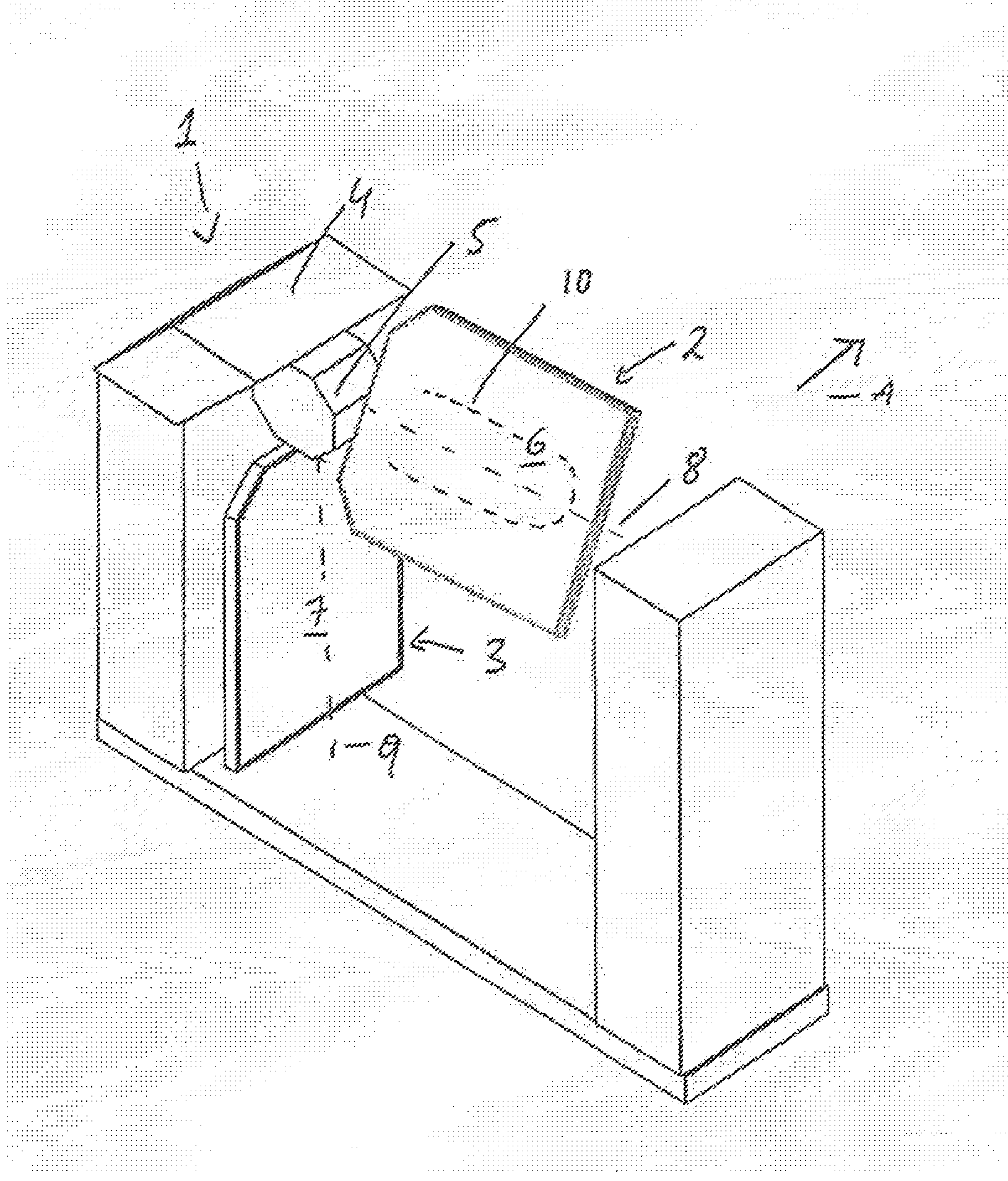
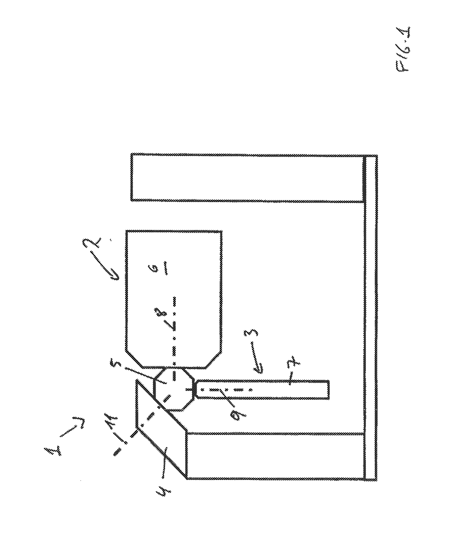
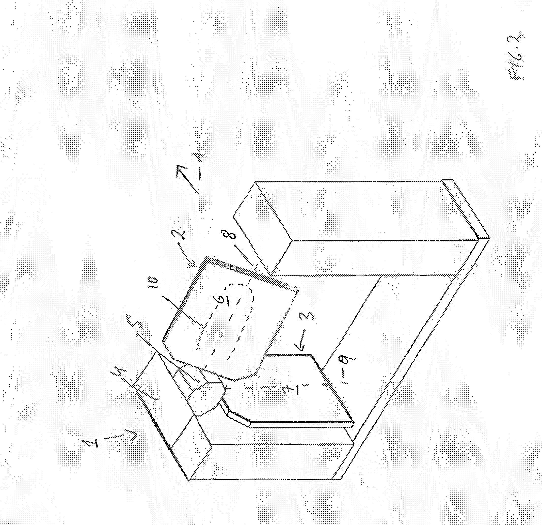
[0028]The preferred embodiments of the present invention will now be described with reference to FIGS. 1-6 of the drawings. Identical elements in the various figures are designated with the same reference numerals.

[0029]FIGS. 1 and 2 show a turnstile 1 constructed according to the invention. It includes two blocking arms 2, 3 connected with a main shaft 5 mounted on a carrier 4. The blocking arms 2, 3 may each assume a blocking position and a free position depending on the rotation of the main shaft 5. In the embodiment shown in FIG. 1, the first blocking arm 2 is in the blocking position while the second blocking arm 3 is in the free position. For the case in which three blocking arms are provided, they are usually positioned at angular separation of 120° from one another (measured by projecting the arms onto a plane perpendicular to the rotating axis), so that each blocking arm may assume one blocking position and two free positions.

[0030]The rotational axis 11 of the main shaft 5...


PUM


Abstract

A personnel access-control device in the form of a turnstile (1) has one or more blocking arms (2, 3) connected to a main shaft (5) mounted in a carrier (4). The blocking arms (2, 3) assume a blocking position and at least one free position in dependence upon the rotation of the main shaft (5). Each blocking arm (2, 3) includes a flat component (6, 7) that is mounted to rotate about its longitudinal axis (8, 9) in dependence upon the rotation of the main shaft (5). In the blocking position of the blocking arms (2, 3), a pre-defined angular position of the flat component (6, 7) with respect to the perpendicular direction is achieved, and in the free position, the flat component (6, 7) is rotated such that passage of a person is allowed and / or that the passage width is not limited.

Description

BACKGROUND OF THE INVENTION[0001]The invention relates to a personnel access-control device in the form of a turnstile for controlling access to a defined area.[0002]Personnel access-control devices are well known in the prior art. For example, a device is known from EP 1 023 608 B1 in which an antenna unit for communication with an RFID (radio-frequency identification device) transponder acts as data medium in which access authorization is stored. Personnel access-control devices further includes a blocking device actuated via a control circuit by an actuator in order to allow a person to enter or exit a building or controlled space. For this, the blocking device is released from a blocking position into a free position upon readout of a valid access authorization. In the free position, access is provided to a person, and / or the width of a passage is not restricted. In contrast, access is denied in the blocking position. In such access-control devices, a turnstile is often used as ...

Claims


Application Information

Patent Timeline
Patent Type & Authority Applications(United States)
IPC IPC(8): E06B11/08E05F15/20
CPCE05F15/2023E06B11/08E05F15/73G07C9/10
Inventor HARUCKSTEINER, GUIDOLEITNER, MARKUSSURKAU, REINHARD
Owner SKIDATA AG
Learn More