Electric Lighting Devices

a technology of lighting devices and lighting elements, applied in the direction of lighting support devices, free standing, lighting and heating apparatus, etc., can solve the problems of significant reduction of achieve realistic flame effect, reduce the attractiveness of the device, and realistic effect of flame

Inactive Publication Date: 2014-04-10
CANDELLA
View PDF5 Cites 9 Cited by
  • Summary
  • Abstract
  • Description
  • Claims
  • Application Information

AI Technical Summary

Benefits of technology

[0011]In one aspect of the inventive subject matter, an electric lighting device comprises an a candle shape housing, a movable flame element coupled to an upper portion of the housing and disposed such that the flame element at least partially extends from the upper portion, and a light source configured to emit light on to the flame element. A curved arm can couple the lighting device to a weight element, which is selected to help maintain a substantially vertical position of the electric lighting device. Where the device includes a movable flame element, it is critical that the device be displayed in a substantially vertical position to ensure that the flame element can properly move to produce a realistic flame effect. If the device is oriented in a non-substantially vertical position, the effect will typically be diminished or destroyed, which significantly reduces the attractiveness of the device.
[0012]In other contemplated embodiments, a string of lighting devices can be provided with each lighting device individually producing a realistic flame effect. Each of the lighting devices can be electrically coupled to one another. In some contemplated embodiment, the lighting devices can each include an aperture through which a wire or other object can pass through, allowing the lighting devices to freely rotate about the wire. In such embodiments, it is further contemplated that each of the devices can have a bottom portion having a greater weight than the devices' upper portions. This advantageously utilizes gravity by causing the lighting devices to rotate until the devices are each in a substantially vertical position. For example, by stringing the wire across branches of a tree, the string of lighting devices can each be maintained a substantially vertical position about the wire. In one embodiment, each lighting device can be coupled to or include a weight element to maintain a substantially vertical position, even where the string of lights is hung in a non-horizontal configuration.
[0013]It is further contemplated that the lighting devices could comprises a housing having a flame element extending therefrom, and a fastener coupled to the housing, such that the lighting devices can each be attached to a object or surface. In one preferred embodiment, the fastener can include a clip, which quickly allows the lighting devices to be clipped to a branch or other object or surface. However, a hook or any other commercially suitable fastener(s) could be used. In such embodiments, it is especially preferred that the device includes a ball joint or other component such that the housing can be oriented into a desired position, typically a substantially vertical position.

Problems solved by technology

If the device is oriented in a non-substantially vertical position, the effect will typically be diminished or destroyed, which significantly reduces the attractiveness of the device.

Method used


Image

  • Electric Lighting Devices
  • Electric Lighting Devices
  • Electric Lighting Devices

Examples


Embodiment Construction

[0027]The following discussion provides many example embodiments of the inventive subject matter. Although each embodiment represents a single combination of inventive elements, the inventive subject matter is considered to include all possible combinations of the disclosed elements. Thus if one embodiment comprises elements A, B, and C, and a second embodiment comprises elements B and D, then the inventive subject matter is also considered to include other remaining combinations of A, B, C, or D, even if not explicitly disclosed.

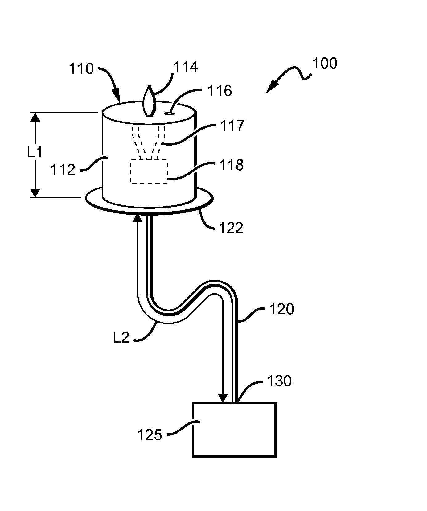
[0028]FIG. 1 is a schematic of one embodiment of an electric lighting device 100 of the inventive subject matter. Electric lighting device 100 comprises an electric candle 110 and an arm 120 coupled with a weight element 125. Optionally, device 100 can include a base 122 that in some contemplated embodiments can be configured to provide the appearance of a bobeche or drip protector often used with traditional wax candles.

[0029]It is contemplated that the ca...


PUM


Abstract

Electric lighting devices having a counterweight are provided. One or more electric candles can be coupled to one or more counterweight elements configured to ensure that the electric candles maintain a substantially upright or vertical position when displayed.

Description

[0001]This application claims the benefit of priority to U.S. Provisional Application No. 61 / 756,300, filed on Jan. 24, 2013, and U.S. Provisional Application No. 61 / 643,076, filed on May 4, 2012. These and all other extrinsic materials discussed herein are incorporated by reference in their entirety. Where a definition or use of a term in an incorporated reference is inconsistent or contrary to the definition of that term provided herein, the definition of that term provided herein applies and the definition of that term in the reference does not apply.FIELD OF THE INVENTION[0002]The field of the invention is electric lighting devices, especially electric candles.BACKGROUND[0003]The following background discussion includes information that may be useful in understanding the present invention. It is not an admission that any of the information provided herein is prior art or relevant to the presently claimed invention, or that any publication specifically or implicitly referenced is...

Claims


Application Information

Patent Timeline
Patent Type & Authority Applications(United States)
IPC IPC(8): F21V21/108F21V21/14
CPCF21V21/145F21V21/108F21S6/001F21V21/14F21V21/088F21W2121/00
Inventor THOMPSON, JEFF
Owner CANDELLA
Why Eureka
Try Eureka