Candle stand with faux flame

a faux flame and candle stand technology, applied in free standing, semiconductor devices of light sources, lighting and heating apparatus, etc., can solve the problem that the visual effect is far from satisfactory to emulate the realistic effect of an actual flame, and achieve the effect of maintaining realistic visual results

Inactive Publication Date: 2015-07-07
GLOBAL RICH INVESTMENT CO LTD
View PDF10 Cites 19 Cited by
  • Summary
  • Abstract
  • Description
  • Claims
  • Application Information

AI Technical Summary

Benefits of technology

[0005]The primary object of the present invention is to provide a lamp with realistic faux flame to replace the actual candle and oil lamp while maintenance realistic visual result.
[0008]Preferably, a coupling axis is disposed horizontally inside the vertical via hole, and the flame decorative element is disposed with a coupling hole at the center segment so that the coupling axis passes through the coupling hole. As such, the flame decorative element is suspended on the coupling axis loosely so that the flame decorative element can move along the coupling axis as well as rotate around the coupling axis to create realistic visual effect of a flame.
[0011]Preferably, the driving element is a rotational axis and at least two leaves. The leaves are fixed to the upper end of the rotational axis, and the lower end of the rotational axis is connected to the output end of the motor. At least one of the second resistive magnet body is fixed to the surface of the leaves, preferably at location near the edge of the leaves and away from the rotational axis. The rotational axis is used to drive the leaves to rotate so that the location of the second resistive magnet body is changed to realize the object of being closer to or away from the first resistive magnet body. In addition, the wind caused by the rotation of the two leaves will blow through the via hole of the holder towards the flame decorative element to enhance the visual effect of the swaying flame.
[0012]Preferably, the first resistive magnet body and the second resistive magnet body are both permanent magnets. The permanent magnets do not require the electricity-excited magnetic field to cause magnetic force between the first resistive magnet body and the second resistive magnet body, which simplifies the structure as well as saves energy.
[0014]Preferably, the candle stand with faux flame further includes a lamp shade. The lamp shape has a cylinder structure with opening at the top. The lamp shade covers on the outside of the lamp stand, the support frame and the holder. The flame decorative element passes through the opening and extends beyond the lamp shade. The lamp shade can provide protection to the lamp stand, the support frame and the holder, as well as additional aesthetic effect to enhance the realistic visual effect of a flame.
[0015]Preferably, the candle stand with faux flame further includes a gearbox, with an input end connected to the output end of the motor and an output end connected to the driving element. The gearbox is to reduce the output rotation speed of the motor so as to adjust the speed of the driving element and the swaying frequency of the flame decorative element to further enhance the realistic effect.

Problems solved by technology

However, as the candle and oil lamp poses potential danger if not carefully handled, the lamps with faux flame are developed.
However, as the flame created by the flame-shaped shade or bulb appears fixed, the visual effect is far from satisfactory to emulate the realistic effect of an actual flame.

Method used


Image

  • Candle stand with faux flame
  • Candle stand with faux flame
  • Candle stand with faux flame

Examples


Embodiment Construction

[0025]The following refers to the drawings to describe the preferred embodiments of the present invention.

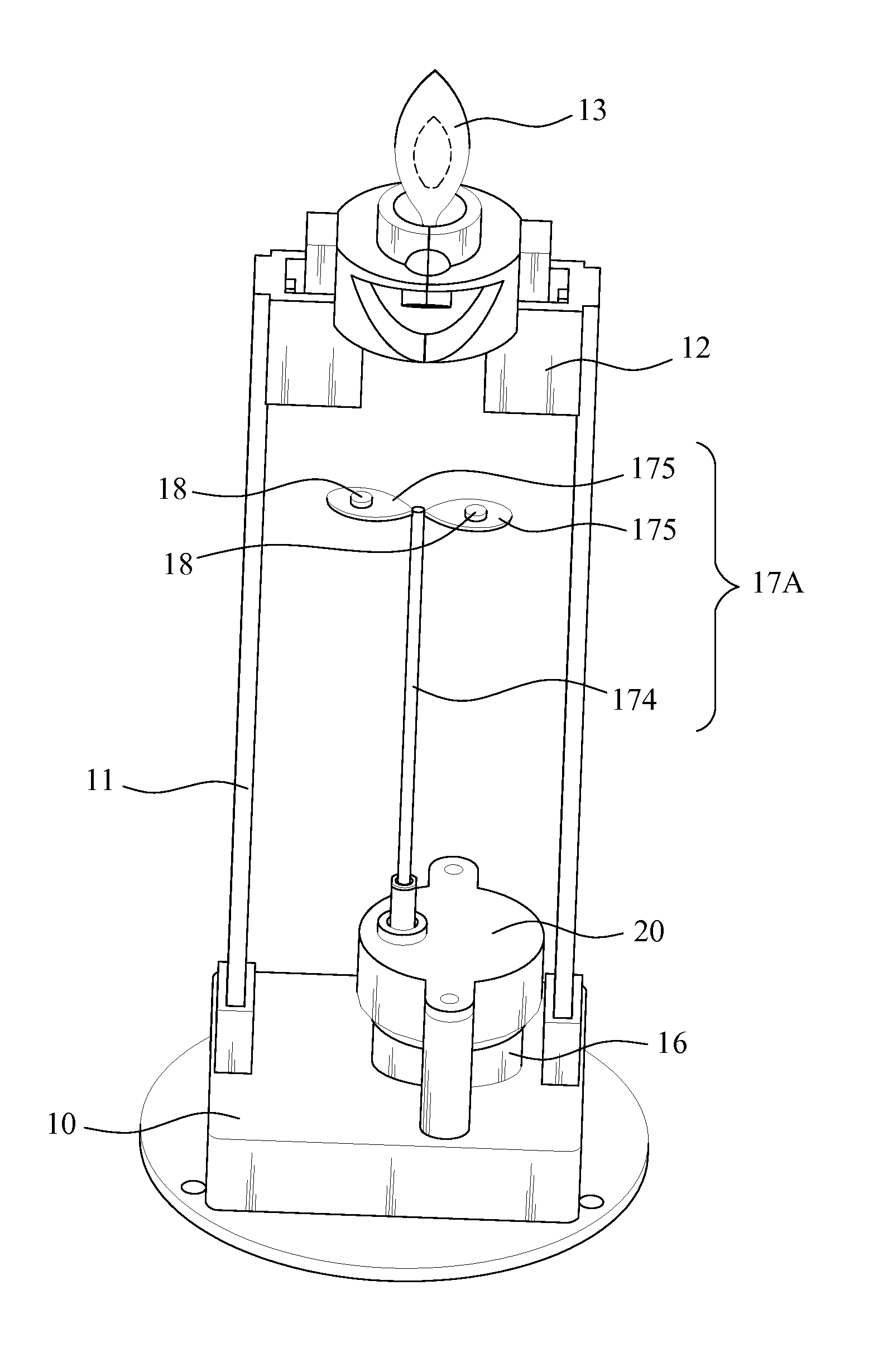
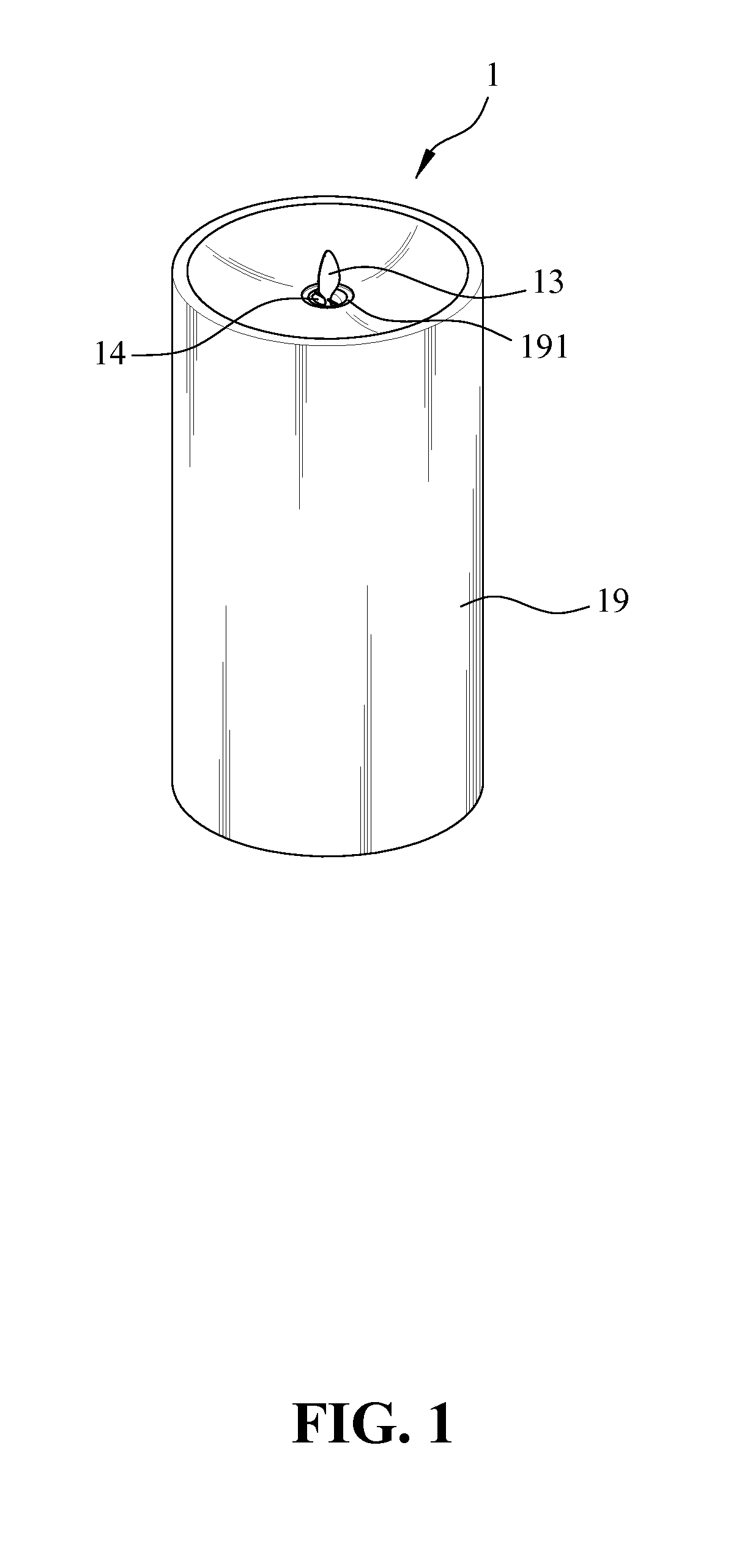
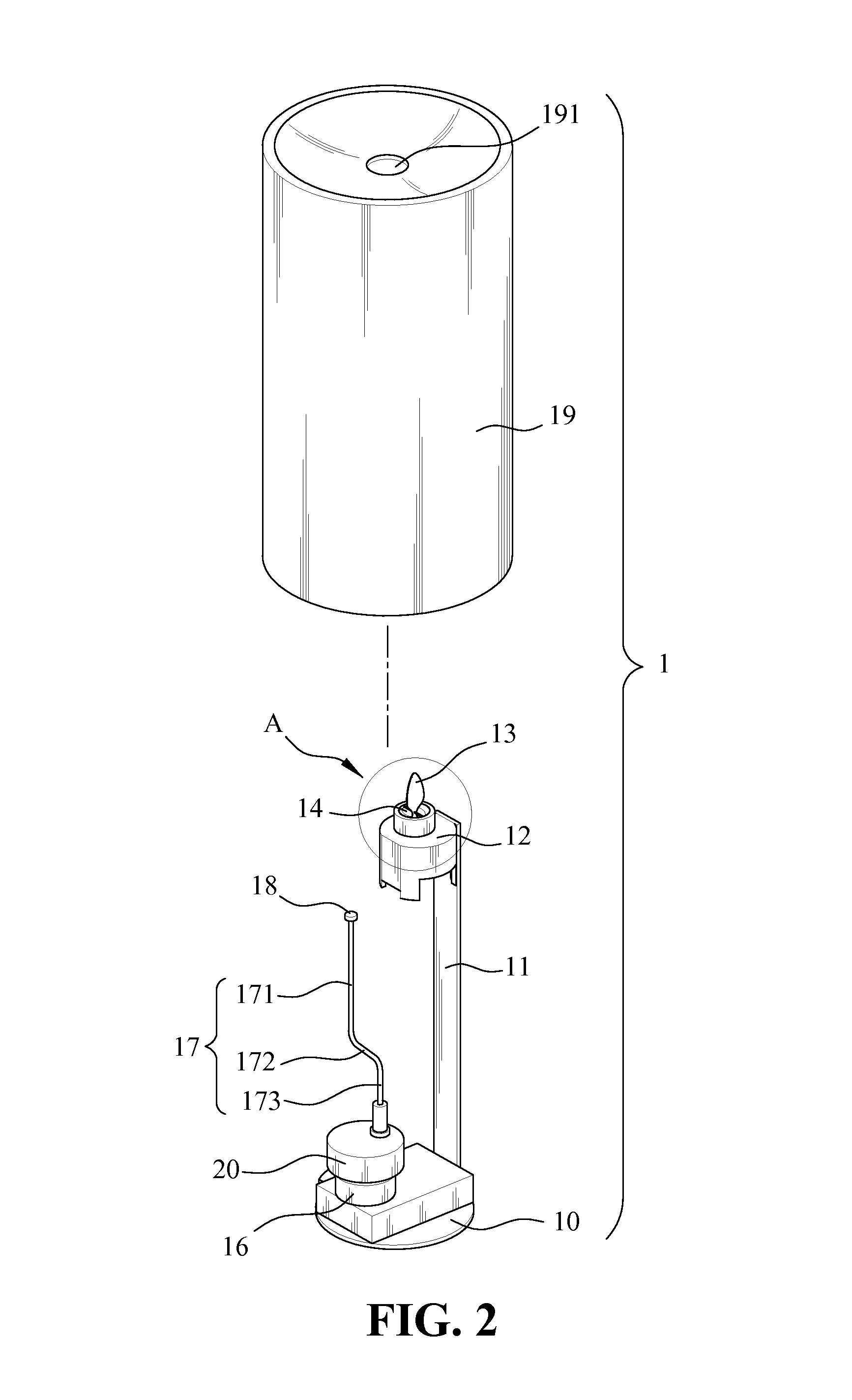
[0026]As shown in FIG. 1 and FIG. 2, a candle stand with faux flame 1 of the present invention includes: a lamp stand 10, a support frame 11, a holder 12, a flame decorative element 13, a light-emitting body 14, a first resistive magnet body 15, a motor 16, a driving element 17, at least a second resistive magnet body 18, and a power supply (not shown). The candle stand with faux flame 1 may further include a lamp shade 19 and a gearbox 20. The light-emitting body 14 is a light-emitting diode (LED) of a bullet head shape. The first resistive magnet body 15 and the second resistive magnet body 18 are both permanent magnets.

[0027]As shown in FIG. 3, the lamp stand 10 includes a battery chamber 101 at bottom for accommodating the power supply. The support frame 11 is fixedly standing upon the lamp stand 10. The holder 12 is fixedly connected to the top of the support frame 11. As s...


PUM


Abstract

A candle stand with faux flame is disclosed, including a lamp stand, power supply, support frame, holder, flame decorative element, light-emitting body, motor, driving element, first resistive magnet body, and at least a second resistive magnet body. The support frame is fixedly standing upon lamp stand; the flame decorative element is suspended at top of holder; the light-emitting body emits light towards flame decorative element. The power supply and motor are inside lamp stand for driving the driving element. The first resistive magnet body is disposed at lower end of flame decorative element. The second resistive magnet body is disposed on the driving element. When the motor drives the driving element, the second resistive magnet body moves close to or away from first resistive magnet body so as to sway flame decorative element. With projected light, the swaying flame decorative element emulates a flame.

Description

FIELD OF THE INVENTION[0001]The present invention generally relates to a lamp technique, and more specifically to a lamp with visual effect of faux flame.BACKGROUND OF THE INVENTION[0002]While the traditional candle and oil-lamp are no longer in wide use, the traditional meaning and unique ambience associated with candle and oil lamp are still irreplaceable by the modern light bulb lamp; in particular, in many religious rituals, burning incense, candle or oil lamp is still considered as part of the important auspicious offering for spiritual cleansing. In addition, the flickering flame on the candle stick or oil lamp is considered to have a calming effect to soothe the weariness and fatigue for various occasions. However, as the candle and oil lamp poses potential danger if not carefully handled, the lamps with faux flame are developed.[0003]The known lamp with faux flame is usually made into a shape of candle stand, with a flame-shape shade or bulb. A light-emitting body is placed ...

Claims


Application Information

Patent Timeline
Patent Type & Authority Patents(United States)
IPC IPC(8): F21V35/00F21S6/00F21Y101/02
CPCF21V35/00F21S6/001F21Y2101/02F21W2121/00F21Y2115/10
Inventor LAI, WEN-CHENG
Owner GLOBAL RICH INVESTMENT CO LTD
Why Eureka
Try Eureka