Candlelight-simulation electronic candle

A technology for simulating electronics and candles, applied in the field of electronic light-emitting devices, can solve the problems of unrealistic flames and unrealistic visual experience, and achieve realistic visual effects and realistic visual experience

Inactive Publication Date: 2014-12-24
戴寿朋 +2
View PDF6 Cites 6 Cited by
  • Summary
  • Abstract
  • Description
  • Claims
  • Application Information

AI Technical Summary

Problems solved by technology

However, when there is no electricity, the swinging mechanism and the light-emitting elements stop working, and the flame sheet looks very unreal, which is very different from the state when the real candle is extinguished, and people can often recognize the device as a candle at a glance. The fake candle device can't be real, the visual experience is not real enough

Method used


Image

  • Candlelight-simulation electronic candle
  • Candlelight-simulation electronic candle
  • Candlelight-simulation electronic candle

Examples


Embodiment 1

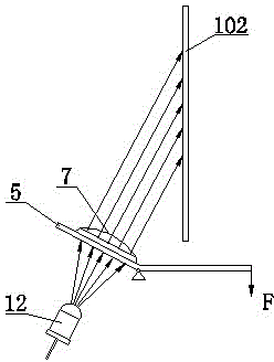
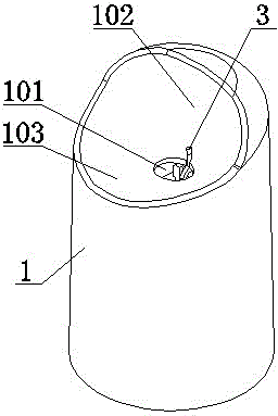
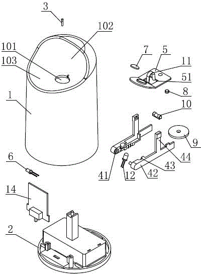
[0032] Such as Figure 2~Figure 6 As shown, a candle simulates an electronic candle, comprising a candle body shell 1 and a candle body base 2, the candle body shell 1 is connected to the candle body base 2, and the candle body shell 1 and the candle body base 2 form an accommodating space, and the candle body The upper end of the body shell 1 is provided with a wick 3, a casing through hole 101 and a background wall 102, wherein the wick 3 is a shape that simulates a real candle wick, and the wick 3 is arranged between the casing through hole 101 and the background wall 102. The accommodating space is equipped with a fixed frame 4 and a lens fixed seat 5, and the fixed frame 4 and the lens fixed seat 5 are hinged. The accommodating space is also equipped with a swing mechanism for driving the lens fixed seat 5 to swing around the fixed frame 4. 5 are installed with a light emitting element 12 and a lens 7 respectively. When the power is turned on, the light from the light emi...

Embodiment 2

[0045] The technical solution of the present embodiment is basically the same as the technical solution of the first embodiment, the difference is:

[0046] Such as Figure 7 As shown, the oscillating mechanism includes a fan 15 installed in the accommodating space, and the lens holder 5 is provided with a windward baffle 16 , and when the power is turned on, the wind generated by the fan 15 drives the baffle 16 to swing. Specifically, the lens holder 5, the lens 7 and the baffle 16 are fixed to each other, and when the wind force generated by the fan 15 drives the baffle 16 to swing, the lens holder 5 and the lens 7 will also swing thereupon, thereby achieving the goal on the background wall 102. The purpose of light and shadow flickering.

[0047] The main technical solution of this embodiment is basically the same as that of Embodiment 1, and the features not explained in this embodiment are explained in Embodiment 1, and will not be repeated here.

Embodiment 3

[0049] The technical solution of the present embodiment is basically the same as the technical solution of the first embodiment, the difference is:

[0050] Such as Figure 8 As shown, the swing mechanism includes a motor 17 installed in the accommodation space, the lens holder 5 is provided with a swing arm 18, and the motor shaft sleeve is provided with a cam 19 that can interfere with the swing arm 18. When the power is turned on, the motor 17 drives the cam 19 Rotating, the cam 19 drives the swing arm 18 to swing. Specifically, the swing arm 18 is arranged on the rotation path of the cam 19. When the motor 17 drives the cam 19 to rotate, the cam 19 will intermittently collide with the end of the swing arm 18, so that the swing arm 18 swings in disorder, and the lens holder 5 and the lens 7 will also swing accordingly, so that the light and shadow on the background wall 102 will fluctuate.

[0051] The main technical solution of this embodiment is basically the same as th...


PUM


Abstract

The invention relates to the technical field of an electronic illuminator, in particular to a candlelight-simulation electronic candle, which comprises a candle body case and a candle body base, wherein the candle body case is connected with the candle body base, the candle body case and the candle body base form an accommodating space, the upper end of the candle body case is provided with a lamp wick, a machine case through hole and a background wall, the lamp wick is arranged between the machine case through hole and the background wall, the accommodating space is provided with a fixing frame and a lens fixing seat, the fixing frame is hinged with the lens fixing seat, the accommodating space is also provided with a swinging mechanism used for driving the lens fixing seat to swing around the fixing frame, the fixing frame and the lens fixing seat are respectively provided with a light emitting element and a lens, in the electrified state, light rays of the light emitting element sequentially pass through the lens and the machine case through hole, and the light rays emitted out from the machine case through hole are projected onto the background wall. The candlelight-simulation electronic candle provided by the invention has the advantages that the use effect of the candle can be really simulated both in the electrified state and in the power failure state, the effect is like real candlelight, and the visual experience is more vivid.

Description

technical field [0001] The invention relates to the technical field of electronic light-emitting devices, in particular to a candlelight simulating an electronic candle. Background technique [0002] In daily life, people originally regarded candles as a kind of lighting fixtures, but with the widespread use of electric light sources, their lighting functions have gradually faded, and people's demand for candles has also changed from practicality to ornamental or interesting, so it appears Various electronic light-emitting devices such as electronic flashing candles, musical candles, and simulated kerosene lamps have been developed. [0003] The prior art discloses an electronic candle, which includes a light-emitting element, a flame piece, and a swing mechanism that can drive the flame piece to shake. The shape of the flame piece is to simulate the real flame shape of a candle after it is lit. After electrification, the flame sheet shakes under the action of the swing me...

Claims


Application Information

Patent Timeline
Patent Type & Authority Patents(China)
IPC IPC(8): F21S10/04F21V14/06F21V23/00F21V11/12
CPCF21S10/04F21S6/001F21S9/02F21W2121/00
Inventor 刘长镕
Owner 戴寿朋
Why Eureka
Try Eureka