Flame simulation light with an inner light source surrounded by light emitting plates

a technology of light emitting plates and flame simulation, which is applied in the field of flame simulation lights, can solve the problems of preventing the popularization and application the flame effect of conventional flame simulation lights is not realistic, and the light effect is not good, so as to achieve good lighting atmosphere

Active Publication Date: 2021-05-04
FUJIAN QUANZHOU FANTA CRAFTS CO LTD
View PDF10 Cites 0 Cited by
  • Summary
  • Abstract
  • Description
  • Claims
  • Application Information

AI Technical Summary

Benefits of technology

[0047]The light-emitting plates have an outer flame effect at its outer sides. The inner light source emits light in the cavity, and the light is projected outwardly through the gaps to have the inner flame effect. Therefore, a flame is simulated more realistically compared with conventional flame simulation light. Further, different light effects can be observed from different angles, which makes the flame simulation light more interesting and creates a good lighting atmosphere.
[0

Problems solved by technology

However, the flame effect of conventional flame simulation lights is not realistic and the light effect i

Method used


Image

  • Flame simulation light with an inner light source surrounded by light emitting plates
  • Flame simulation light with an inner light source surrounded by light emitting plates
  • Flame simulation light with an inner light source surrounded by light emitting plates

Examples


embodiment i

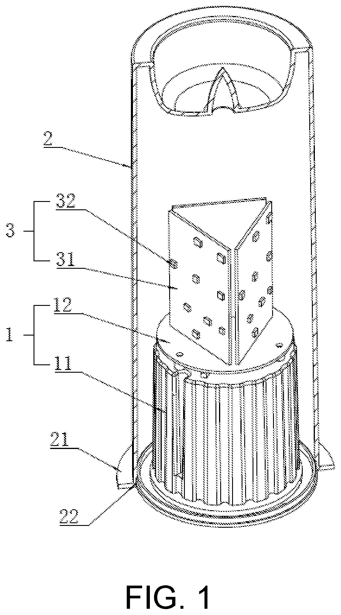
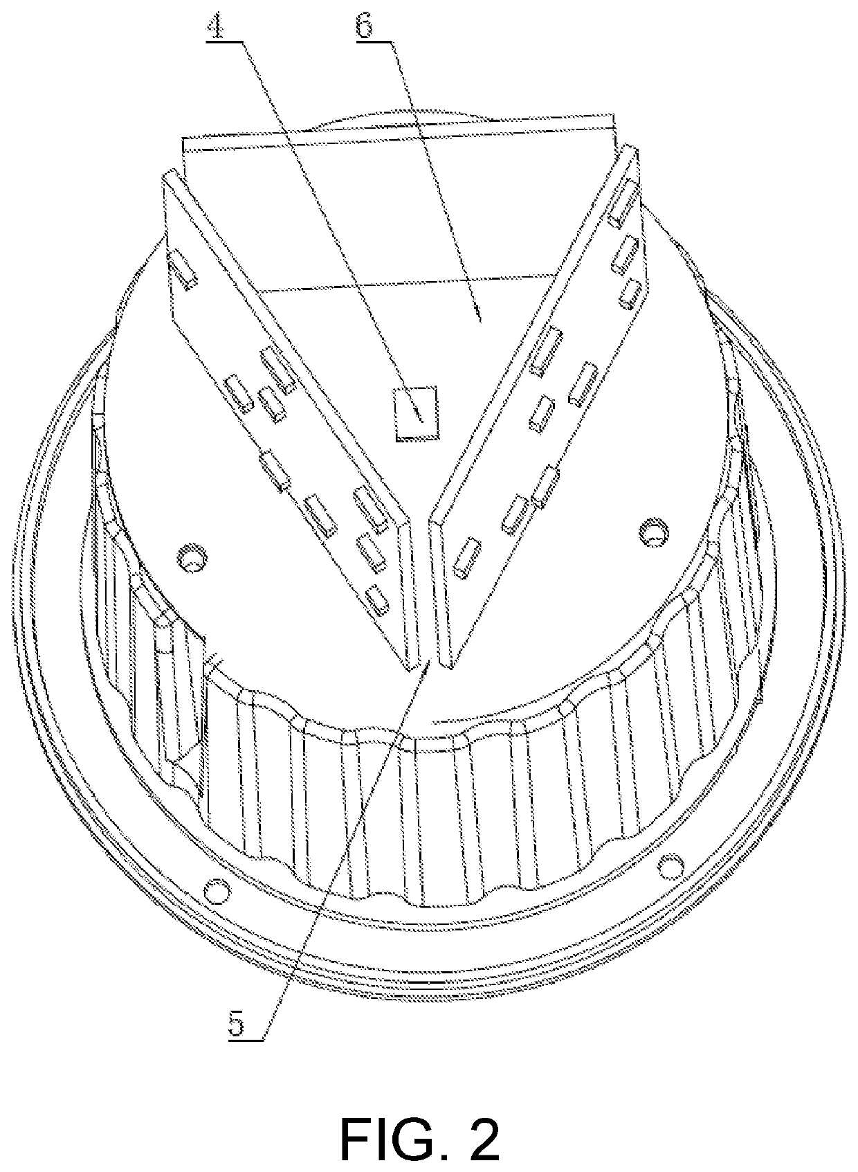
[0063]Referring to FIG. 1 and FIG. 2, the present application relates to a flame simulation light. The flame simulation light includes a light base 1 and a light housing 2. The bottom of the light housing 2 is provided with an outer ring 21 that extends radially outwardly from the outer wall of the bottom, such that screw is fixed. The light housing 2 covers the light base 1 at the peripheral side of the light base 1. A groove 22 is arranged in the inner side of the bottom of the light housing 2. The peripheral side of the bottom of the light base 1 is engaged in the groove 22 and is glued to the light housing 2.

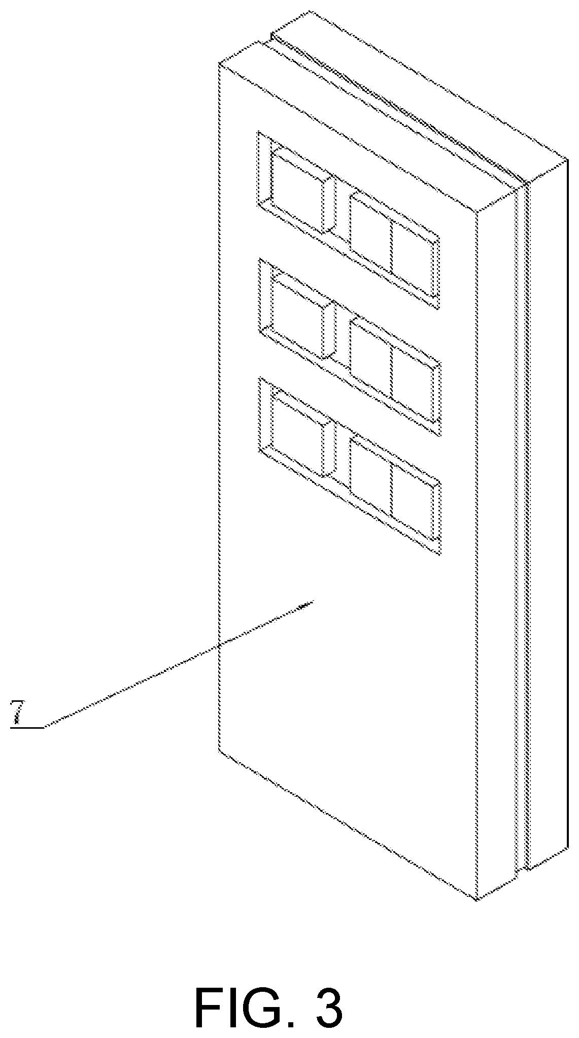
[0064]The light housing 1 includes a battery case 11 and a substrate 12 that is electrically connected to the top of the battery case 11. Three light-emitting plates 3 are vertically arranged on the substrate 12 of the light base 1 and are electrically connected to the light base 1. The light emitting surfaces of the light-emitting plates 3 face outward, while the back surfa...

embodiment ii

[0069]Embodiment II is different from embodiment I in the following aspect. The inner light source 4 can be colored light bead emitting light of a plurality of colors.

embodiment iii

[0070]Embodiment III as shown in FIG. 4 is different from embodiment I in the following aspects. The inner light source 4 can be a light group having three primary-color light beads or sheet-like light sources. The three light beads or the sheet-like light sources are arranged to surround the center of the cavity 6. Each of light beads or sheet-like light sources respectively corresponds to the center of each light-emitting plate 3.


PUM


Abstract

A flame simulation light comprises a light base and a light housing. The light base is provided with a plurality of light-emitting plates extending in the direction away from the light base. The adjacent light-emitting plates are arranged end to end and enclose a cavity with gaps. At least an inner light source is arranged in the cavity to emit light through the gaps. Therefore, a flame is simulated more realistically compared with conventional flame simulation light. Further, different light effects can be observed from different angles, which makes the flame simulation light more interesting. In addition, this manner of simulating flame can have diverse flame effects by changing inclination, arc, height, width, or shape of the light-emitting plates. In terms of the effect of having inner and outer flames, various combinations are possible. Compared with conventional integral flame simulation light, this flame simulation light realizes diversity.

Description

CROSS-REFERENCE TO RELATED APPLICATION[0001]This application claims the priority benefit of China application No. 202020478485.6, filed on Apr. 3, 2020. The entirety of the above-mentioned patent application is hereby incorporated by reference herein and made a part of this specification.BACKGROUNDTechnical Field[0002]The present invention relates to a technical field of light, in particular to a flame simulation light.Description of Related Art[0003]As society advances, people's quality of life is being improved. Decorative lights are used not only for illumination, but also for decorative purposes, which brings the sense of beauty.[0004]A flame simulation light is used to simulate flame. Since there is no combustion product that is harmful to environment and human health and there is no fire risk, the flame simulation light can be widely used for decorating party, home, environment and the like. However, the flame effect of conventional flame simulation lights is not realistic and...

Claims


Application Information

Patent Timeline
IPC IPC(8): F21S10/04F21Y107/50F21S6/00
CPCF21S10/043F21S6/001F21Y2107/50F21V23/0435F21Y2115/10
Inventor HE, KE
Owner FUJIAN QUANZHOU FANTA CRAFTS CO LTD
Why Eureka
Try Eureka