Improved structure for light emitting diode (LED) lamp tube

A technology for LED lamp tubes and improved structures, which can be applied to lampshades, parts of lighting devices, semiconductor devices of light-emitting elements, etc., and can solve problems such as black areas

Inactive Publication Date: 2014-03-05
JIANGSU SUN & MOON LIGHTING +1
View PDF13 Cites 0 Cited by
  • Summary
  • Abstract
  • Description
  • Claims
  • Application Information

AI Technical Summary

Problems solved by technology

[0006] The purpose of the present invention is to provide an improved structure of LED lamp tubes to solve the problem of black areas on both sides of the lamp tubes in the prior art LED fluorescent lamps

Method used


Image

  • Improved structure for light emitting diode (LED) lamp tube
  • Improved structure for light emitting diode (LED) lamp tube
  • Improved structure for light emitting diode (LED) lamp tube

Examples


Embodiment Construction

[0034] In order to further explain the technical solution of the present invention, the present invention will be described in detail below through specific examples.

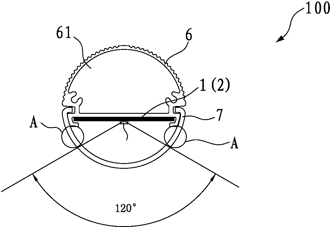
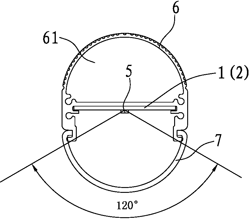
[0035] please compare figure 2 and image 3 As shown, it is a comparison between the prior art and the technical solution of the present application. In the prior art, the LED fluorescent lamp 100 also includes a casing 6 and a PC cover 7. The casing 6 and the PC cover 7 can be interlocked and interlocked Finally, a cavity 61 is formed, and the circuit board is accommodated in the cavity 61. Specifically, in this embodiment, the circuit board is composed of a first substrate 1 and a second substrate 2, that is, the first substrate 1 and the second substrate 2 are all contained in the cavity 61; because the existing LED fluorescent lamp 100 diverges light at 120 degrees, but the PC cover 7 does cover half of the entire shell 6, that is, it covers an angle of 180 degrees. Form a black area A at an angle of 30 ...


PUM


Abstract

An improved LED lamp tube structure includes a shell (6) and a PC cover (7). The shell (6) and a PC cover (7) can be fastened to each other to form a cavity (61). A circuit board (1) is disposed in the cavity (61). A plurality of LEDs (5) is mounted on the circuit board (1) and arranged in the longitudinal direction of the circuit board (1). Each of LEDs (5) has a light-emission angle. The PC cover (7) has an arc angle equal to the light-emission angle. Each of the LEDs (5) extends in a direction perpendicular to the longitudinal direction of the circuit board (1).

Description

technical field [0001] The invention relates to the field of LED fluorescent lamps, and more specifically relates to an improved structure of an LED lamp tube capable of solving the black areas on both sides of the LED fluorescent lamp. Background technique [0002] With the continuous development of domestic LED technology, many manufacturers are currently considering taking advantage of the talent advantage of low domestic labor force to sell their LED fluorescent lamps to Europe and other overseas countries. However, if they want to sell their products to Europe, they must make their products Meet European product certification. [0003] For example, there is a requirement in the European certification that the distance between the LED lamp in the LED fluorescent lamp and the outer edge of the aluminum substrate is at least 5mm; due to the use of oblique arrangement or a word in the prior art (such as 3014, the length direction of 30 is parallel to the length direction of...

Claims


Application Information

Patent Timeline
Patent Type & Authority Patents(China)
IPC IPC(8): F21S4/00F21V19/00F21Y101/02
CPCF21S4/008F21Y2101/02F21V3/02F21K9/17F21Y2103/003F21V5/02F21S4/003F21K9/27F21S4/20F21S4/28F21V21/005F21V23/06F21Y2103/10F21Y2115/10H05K1/141H05K1/142H05K1/181H05K3/0061H05K2201/10106
Inventor 欧阳伟欧阳杰
Owner JIANGSU SUN & MOON LIGHTING
Why Eureka
Try Eureka