LED traffic lamp control system

a technology of traffic lamps and control systems, applied in the field of system and method of controlling traffic lamps based on power signals, can solve problems such as the complexity of configuration and the control system of traffic lamps, and achieve the effect of accurate control and synchronization of light emission, compact circuitry, and accurate control of light emission

Inactive Publication Date: 2014-04-17
GE LIGHTING SOLUTIONS LLC
View PDF2 Cites 0 Cited by
  • Summary
  • Abstract
  • Description
  • Claims
  • Application Information

AI Technical Summary

Benefits of technology

[0006]Embodiments of the present disclosure provide systems and methods of controlling a traffic lamp based on a power signal. Unlike prior systems where control of the timing sequences of the traffic lamp were performed remotely from the traffic lamp, embodiments of the traffic lamp, as described herein, can include a controller coupled with a light emitting element within the traffic lamp. A power signal can be provided to the traffic lamp and the controller can determine a power signal characteristic based on the power signal. The power signal characteristic can be used to control the light emitting timing of the light emitting element. By eliminating a separate and remote control system, embodiments of the present disclosure can be characterized by implementing fewer system devices with more compact circuitry that can more accurately control and synchronize light emission in the traffic lamp.

Problems solved by technology

However, light emitting diodes (LEDs) are replacing the incandescent lamps because of reduced energy consumption and longer life.
This configuration increases the complexity of the traffic lamp control system because additional components and control methods are necessary to synchronize a plurality of lamps within the traffic lamp.

Method used


Image

  • LED traffic lamp control system
  • LED traffic lamp control system
  • LED traffic lamp control system

Examples


Embodiment Construction

[0017]Reference now will be made in detail to embodiments of the invention, one or more examples of which are illustrated in the drawings. Each example is provided by way of explanation of the invention, not limitation of the invention. In fact, it will be apparent to those skilled in the art that various modifications and variations can be made in the present invention without departing from the scope or spirit of the invention. For instance, features illustrated or described as part of one embodiment can be used with another embodiment to yield a still further embodiment. Thus, it is intended that the present invention covers such modifications and variations as come within the scope of the appended claims and their equivalents.

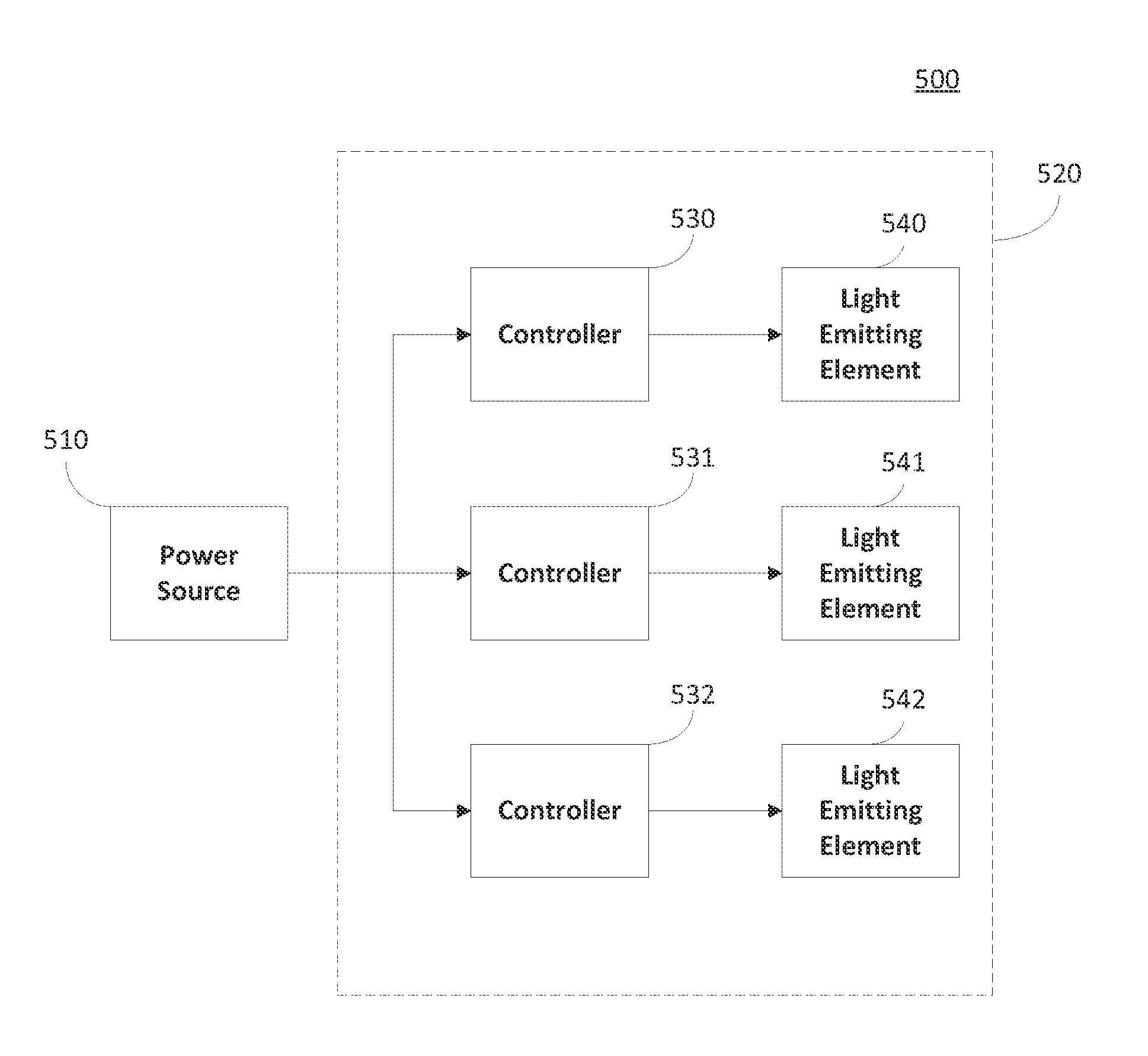
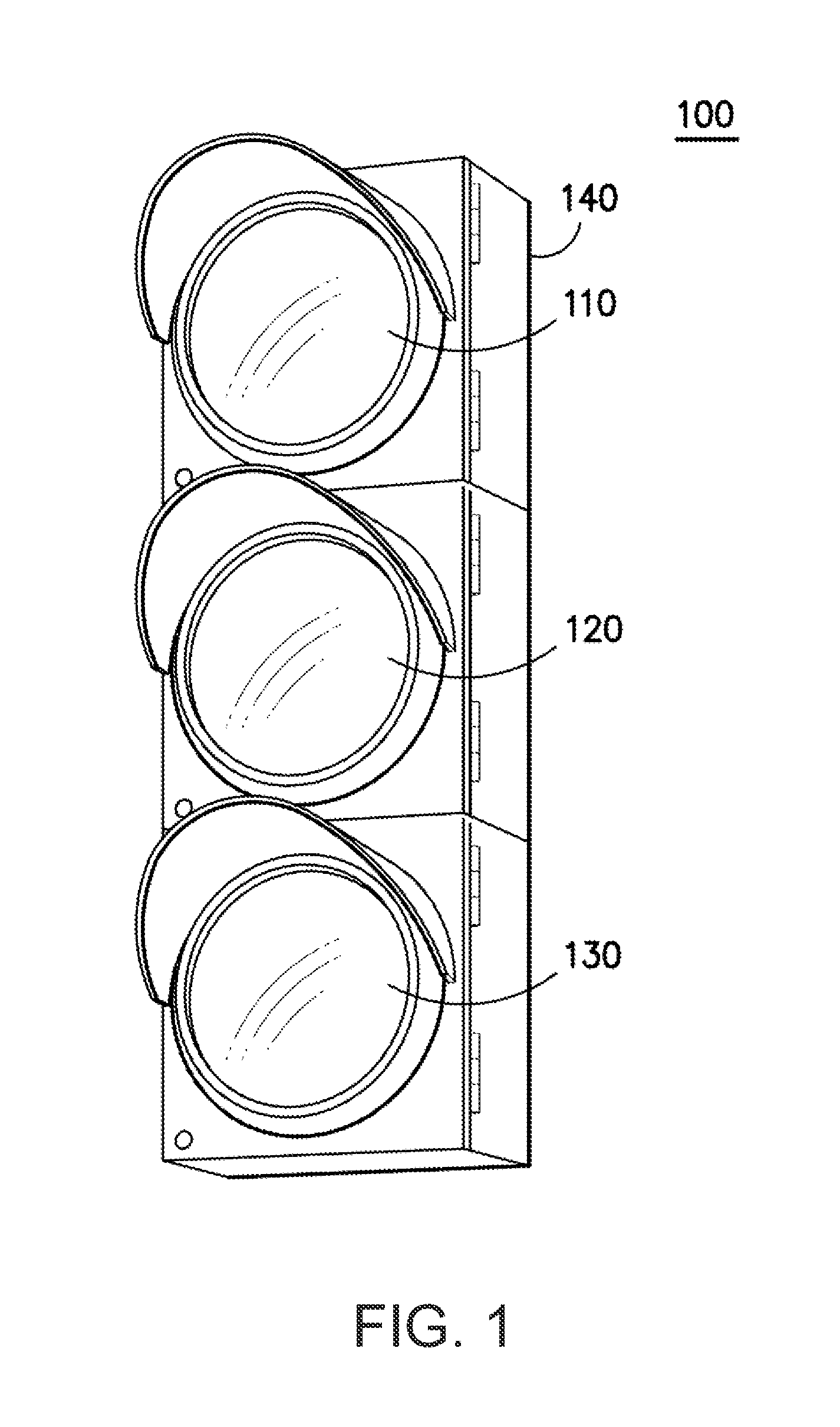
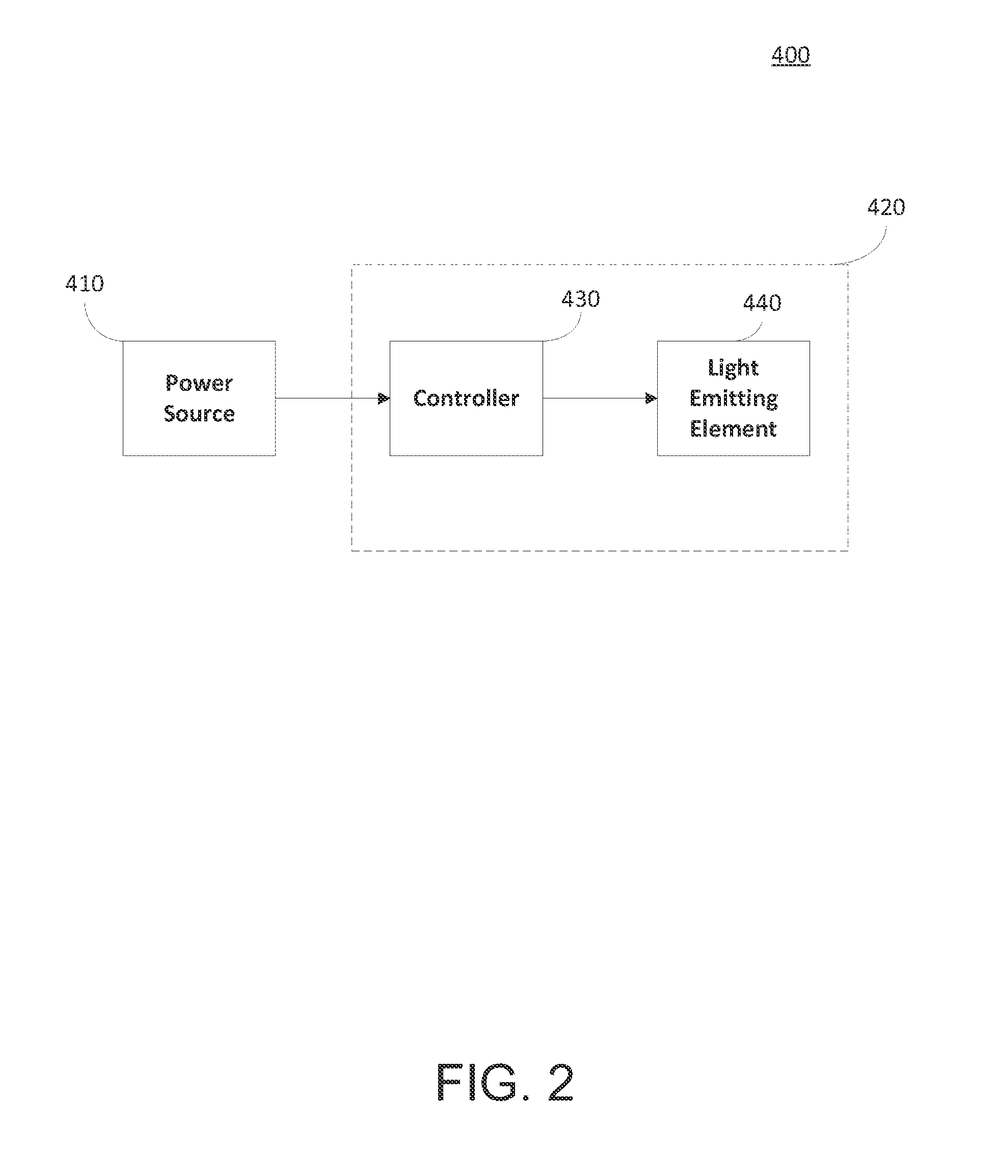
[0018]Generally, the present disclosure is directed to a traffic lamp and a method of controlling the traffic lamp based on a power signal. The traffic lamp can include a controller and a light emitting element. When a plurality of light emitting elements i...


PUM


Abstract

A traffic lamp and a method of controlling the traffic lamp based on a power signal are provided. The traffic lamp can include a controller and a light emitting element. When a plurality of light emitting elements is included in the traffic lamp, each light emitting element is coupled with a separate controller. Each controller can be configured to include a predetermined light emitting timing sequence for the corresponding light emitting element. When the power signal is supplied to the traffic lamp, each controller determines a power signal characteristic such as a frequency or a period of the power signal and controls a light output of the light emitting element based on the power signal characteristic and the light emitting timing sequence. A plurality of light emitting elements can be synchronized using the power signal applied to the traffic lamp.

Description

FIELD OF THE INVENTION[0001]The present disclosure relates to a traffic lamp and more particularly to a system and method of controlling a traffic lamp based on a power signal.BACKGROUND OF THE INVENTION[0002]A traffic lamp can be a signaling device to control traffic flow or to provide an alert or indication to traffic. Traditionally, traffic lamps used incandescent lamps as a light source. However, light emitting diodes (LEDs) are replacing the incandescent lamps because of reduced energy consumption and longer life.[0003]Conventionally, LED traffic lamps are controlled in the same way the incandescent traffic lamps. For instance, a single control box is provided externally to the traffic lamp and is coupled with all the lamps of the traffic lamp. The control box can control the timing of the lights by turning on and off the power signal provided to the lamps of the traffic lamp. This configuration increases the complexity of the traffic lamp control system because additional comp...

Claims


Application Information

Patent Timeline
Patent Type & Authority Applications(United States)
IPC IPC(8): H05B37/02
CPCG08G1/085G08G1/095H05B47/16Y02B20/40
Inventor NESER, MORNENGUYEN, TRUONG-KHOAPOIRIER, CHRISTIAN
Owner GE LIGHTING SOLUTIONS LLC
Why Eureka
Try Eureka