
Ultrasonic C-scanning localization method and device

A scanning positioning and ultrasonic technology, which is used in measurement devices, material analysis using sonic/ultrasonic/infrasonic waves, instruments, etc., can solve the problem of low positioning speed, and achieve high positioning speed, high speed and convenient use.

Active Publication Date: 2014-05-28
CHINA AIRPLANT STRENGTH RES INST
View PDF6 Cites 0 Cited by
  • Summary
  • Abstract
  • Description
  • Claims
  • Application Information

AI Technical Summary

Problems solved by technology

This method realizes positioning without pull wires, but due to the limitation of sound wave propagation speed, its positioning speed is low

Method used

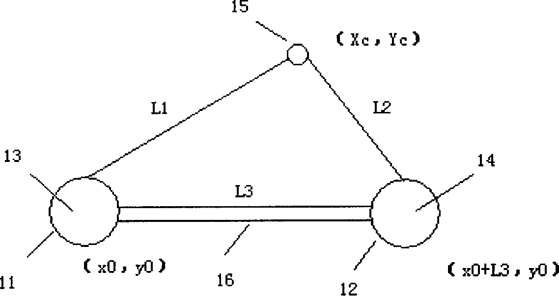
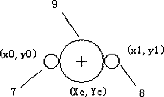

Image

  • Ultrasonic C-scanning localization method and device
  • Ultrasonic C-scanning localization method and device
  • Ultrasonic C-scanning localization method and device

Examples


Embodiment Construction

[0028] The present invention will be further described below by specific embodiment:

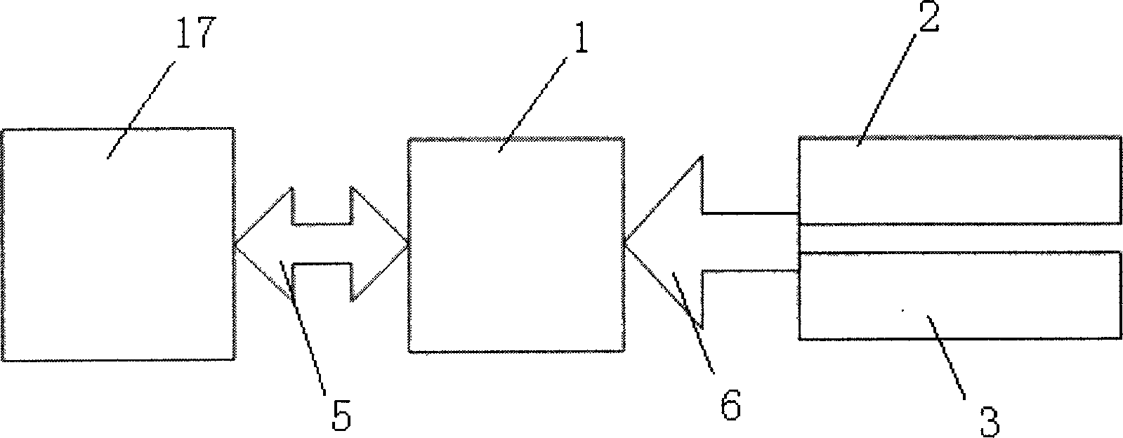
[0029] see figure 2 , which is a system block diagram of the ultrasonic C-scan positioning device of the present invention. The ultrasonic C-scan positioning device includes a CPLD system 1 , a two-way laser sensor circuit 2 , a probe fixture 4 , a communication interface 5 and a serial interface 6 . The CPLD system 1 is EPM3256, which has 4 adders inside. The laser sensor circuit is composed of ADNS9500 laser sensor and surrounding related components, which is used to detect the position change information of the laser sensor itself in real time and send it to the CPLD system. Wherein, the two-way laser sensor circuits are fixed on the probe fixture 4 , and the two-way laser sensor circuits are connected to the CPLD system 1 through the serial interface 6 . The CPLD system 1 is connected with the upper computer 17 through the communication interface 5 to realize the communication with t...


PUM


Abstract

The invention discloses an ultrasonic C-scanning localization device. The ultrasonic C-scanning localization device comprises a CPLD (Complex Programmable Logic Device) system, a probe fixture, a communication interface, a serial interface and two laser sensor circuits, wherein, the two laser sensor circuits are connected with the CPLD system through the serial interface; the CPLD system is connected with an upper computer through the communication interface; and the two laser sensor circuits are symmetrically fixed on the probe fixture. In addition, the invention further provides an ultrasonic C-scanning localization method. The ultrasonic C-scanning localization method has the beneficial effects that on the basis of the design of symmetrical dual sensors, the problem of inaccurate localization during the spinning process of a probe is solved, high precision of the localization device is ensured, and higher localization speed is achieved; and the localization device is simple and convenient in operation.

Description

Technical field: [0001] The invention belongs to the field of non-destructive testing, and relates to positioning during non-destructive testing using an ultrasonic C-scanning method. Background technique [0002] Ultrasonic C-scan is a commonly used non-destructive testing method. During the on-site C-scanning process, the inspector holds the ultrasonic probe and slides the probe on the surface of the test piece for detection, records the damage status of each point in real time, and displays the damage depth information at each point in different colors in real time. Since the sliding trajectory of the probe on the surface of the tested part is random and unknown, it is necessary to locate the position of the probe in real time during the detection process to achieve a one-to-one correspondence between position information and damage information. During the ultrasonic C-scan detection process, the moving speed of the probe determines the speed of detection, and the speed ...

Claims


Application Information

Patent Timeline
Patent Type & Authority Patents(China)
IPC IPC(8): G01N29/26
Inventor 李闵行肖迎春张昭郭佳白玮詹绍正
Owner CHINA AIRPLANT STRENGTH RES INST
Learn More