Reflecting plate for fresnel lens and illumination device

a technology of fresnel lens and reflector, which is applied in the direction of semiconductor devices for light sources, light and heating devices, fixed installations, etc., can solve the problems of deteriorating the optical efficiency of the illumination device and deteriorating the appearance of the illumination device, so as to prevent the appearance deterioration of the illumination device and optimize the irradiation light

Inactive Publication Date: 2014-04-17
MINEBEA CO LTD
View PDF14 Cites 2 Cited by
  • Summary
  • Abstract
  • Description
  • Claims
  • Application Information

AI Technical Summary

Benefits of technology

[0037]Since the present invention is structured as described above, it is possible to prevent deterior

Problems solved by technology

This will eventually cause deterioration of the optical efficiency of the illumina

Method used


Image

  • Reflecting plate for fresnel lens and illumination device
  • Reflecting plate for fresnel lens and illumination device
  • Reflecting plate for fresnel lens and illumination device

Examples


Embodiment Construction

[0044]Hereinafter, each embodiment of the present invention will be described with reference to the drawings. Here, the same or equivalent parts to the related art will be denoted by the same symbols, and their detailed descriptions will be omitted.

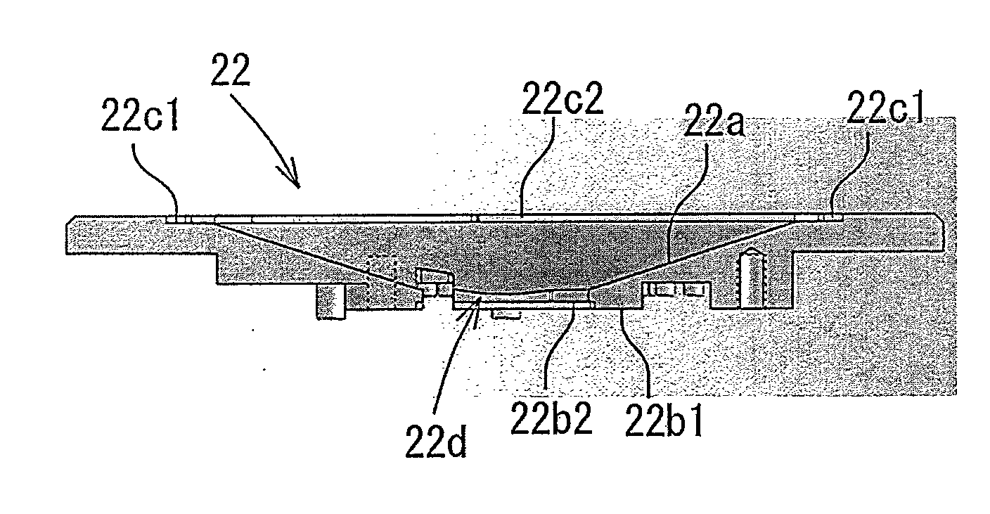
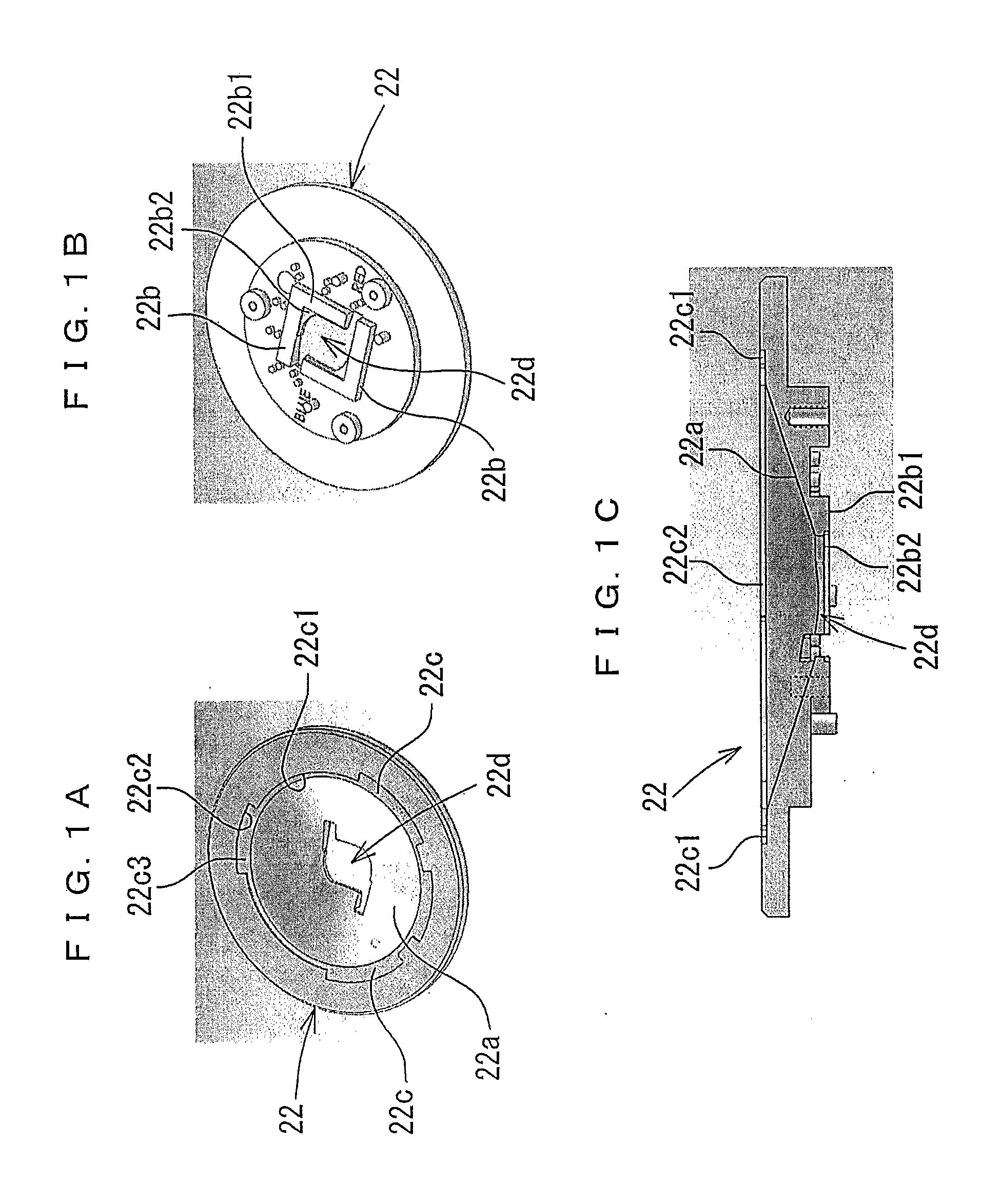
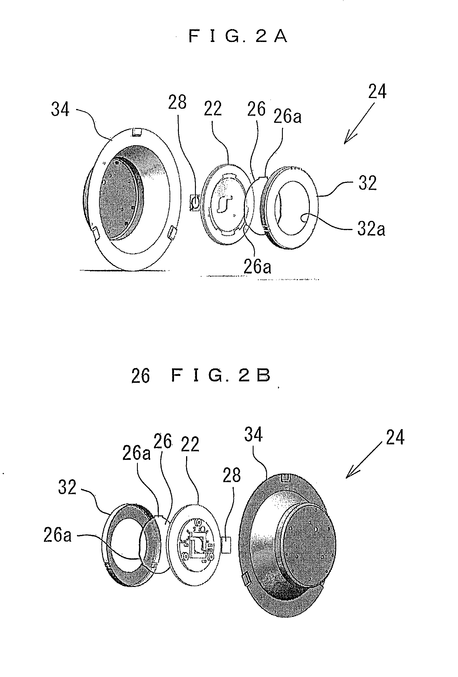
[0045]FIGS. 1A to 1C show a reflecting plate 22 for a Fresnel lens (hereinafter simply referred to as the reflecting plate 22) according to the embodiment of the present invention. FIGS. 2A and 2B to FIGS. 4A to 4C show an illumination device 24 having the reflecting plate 22 in FIG. 1A to 1C.

[0046]As shown in FIGS. 2A and 2B and FIGS. 4A to 4C, the reflecting plate 22 according to the embodiment of the present invention is arranged between a Fresnel lens 26 and a light source 28. The reflecting plate 22 has a concave reflecting surface 22a (FIGS. 1A to 1C) made of a cone-shaped curved surface to reflect light emitted from the light source 28 toward the Fresnel lens 26. The concave reflecting surface 22a is formed into a shape most suitab...


PUM

PropertyMeasurementUnit
Shapeaaaaaaaaaa
Lightaaaaaaaaaa
Reflectanceaaaaaaaaaa

Abstract

There is provided a reflecting plate for a Fresnel lens arranged between the Fresnel lens and a light source, the reflecting plate including: a concave reflecting surface to reflect light emitted from the light source toward the Fresnel lens; a unit to position the light source, the unit being provided at a bottom of the concave reflecting surface; and a unit to position the Fresnel lens, the unit being provided at an open end on a side opposite to the bottom of the concave reflecting surface.

Description

BACKGROUND OF THE INVENTION[0001]1. Field of the Invention[0002]The present invention relates to a reflecting plate used together with a solid light emitting element as represented by a light emitting diode and a Fresnel lens, and an illumination device having these components.[0003]2. Description of the Related Art[0004]In the past, it has been common to use incandescent lamps or fluorescent lamps as light sources for general illumination such as room illumination. However, with the recent high performance of blue light emitting diodes (LEDs), LEDs have also been used as light sources for downlights, spot lights, or the like (see, for example, JP-A No. 2012-119257). Since the LEDs consume less electric power and have longer service lives, they are suitable to respond to requests for the prevention of global warming and environmental conservation.[0005]FIG. 6 exemplifies an illumination device 10 using an LED as a light source. The illumination device 10 is used as a spotlight. In t...

Claims


Application Information

Patent Timeline
IPC IPC(8): F21V13/04
CPCF21V13/04F21V5/045F21V7/04F21Y2105/00F21Y2115/10F21Y2115/20F21Y2115/30F21V7/24F21V7/28
Inventor HOSHI, HIROYAEDAMITSU, TAKASHI
Owner MINEBEA CO LTD
Why Eureka
Try Eureka