Shear reduction mechanism

a technology of protection mechanism and ball bearing, which is applied in chemical protection, nuclear engineering, nuclear elements, etc., can solve the problems of limited protective gear effectiveness

Active Publication Date: 2014-04-24
BRAINGUARD TECH
View PDF4 Cites 39 Cited by
  • Summary
  • Abstract
  • Description
  • Claims
  • Application Information

AI Technical Summary

Problems solved by technology

Nonetheless, the effectiveness of protective gear remains limited.

Method used


Image

  • Shear reduction mechanism
  • Shear reduction mechanism
  • Shear reduction mechanism

Examples


example embodiments

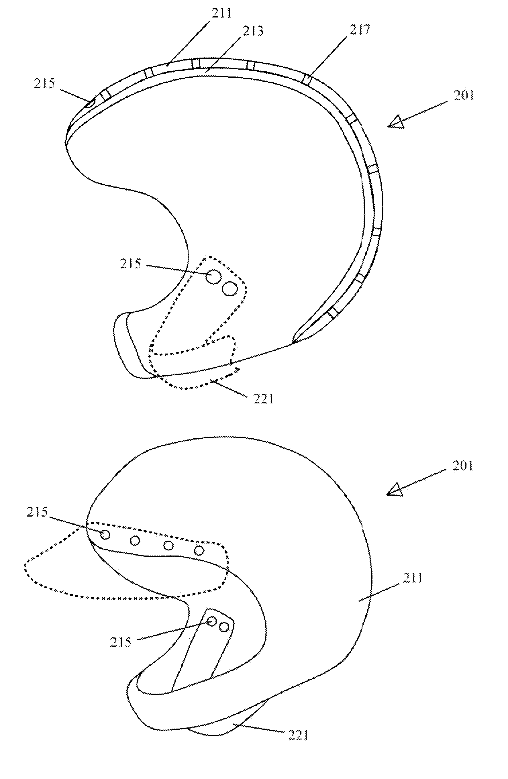
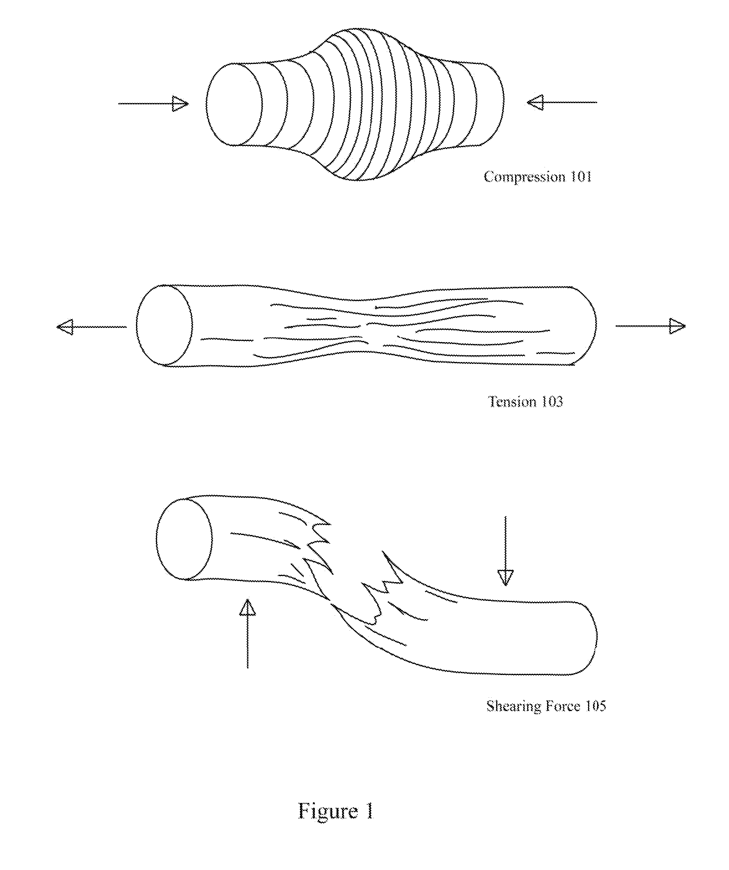
[0017]Protective gear such as knee pads, shoulder pads, and helmets are typically designed to prevent direct impact injuries or trauma. For example, many pieces of protective gear reduce full impact forces that can structurally damage an area of contact such as the skull or knee. Major emphasis is placed on reducing the likelihood of cracking or breaking of bone. However, the larger issue is preventing the tissue and neurological damage caused by rotational forces, shear forces, oscillations, and tension / compression forces.

[0018]For head injuries, the major issue is neurological damage caused by oscillations of the brain in the cranial vault resulting in coup-contracoup injuries manifested as direct contusions to the central nervous system (CNS), shear injuries exacerbated by rotational, tension, compression, and / or shear forces resulting in demyelination and tearing of axonal fibers; and subdural or epidural hematomas. Because of the emphasis in reducing the likelihood of cracking ...


PUM


Abstract

Protective gear such as a helmet includes multiple layers including an outer ball bearing layer and/or one or more energy and impact transformer layers. The ball bearing layer exposes multiple ball bearings on the outer surface of the protective gear to deflect and diminish shear forces and other rotational forces imparted onto the outer surface. In many examples, the ball bearings on the outer surface prevent the transfer of shear and rotational forces from the surface of a helmet onto a skull. The energy and impact transformer layers may also include various structures and materials used to dissipate mechanical energy applied to an outer layer or outer shell layer.

Description

TECHNICAL FIELD[0001]The present disclosure relates to ball bearing shear force reduction protection mechanisms.DESCRIPTION OF RELATED ART[0002]Protective gear such as sports and safety helmets are designed to reduce direct impact forces that can mechanically damage an area of contact. Protective gear will typically include padding and a protective shell to reduce the risk of physical head injury. Liners are provided beneath a hardened exterior shell to reduce violent deceleration of the head in a smooth uniform manner and in an extremely short distance, as liner thickness is typically limited based on helmet size considerations.[0003]Protective gear is reasonably effective in preventing injury. Nonetheless, the effectiveness of protective gear remains limited. Consequently, various mechanisms are provided to improve the ability of protective gear to protect against shear forces and other mechanical forces.BRIEF DESCRIPTION OF THE DRAWINGS[0004]The disclosure may best be understood ...

Claims


Application Information

Patent Timeline
Patent Type & Authority Applications(United States)
IPC IPC(8): A42B3/06A41D13/015A42B3/00
CPCA42B3/064A41D13/015A42B3/122A42B3/04A42B3/10A42B3/063A42B3/08A42B3/121A42B3/125
Inventor KWAN, AVERY AUDREYKNIGHT, ROBERT T.
Owner BRAINGUARD TECH
Why Eureka
Try Eureka